Network and Power Connections
Enterasys Wireless WS-AP3705i Install Guide 2-9
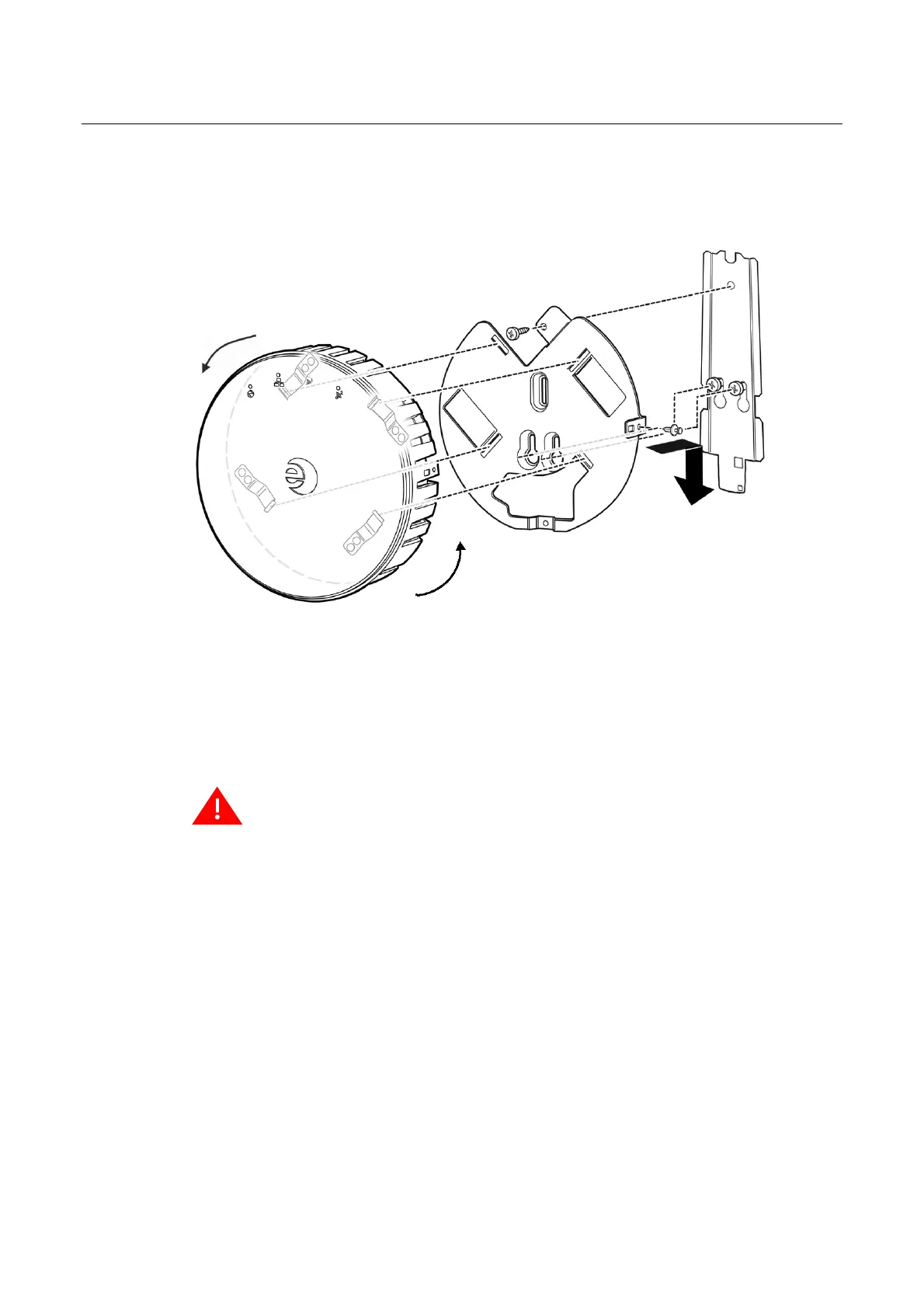
2. Attach the WS-AP3705i mounting bracket to the older mounting bracket, with three screws
through the WS-AP3705i bracket holes into the corresponding holes on the older plate
(
Figure 2-8).
Figure 2-8 Attaching WS-AP3705i mounting bracket to existing AP mount plate.
3. Plug the Ethernet cable into the RJ-45 port on the back of the AP, and if applicable, plug the
power cord into the power port on the back of the AP, before mounting the AP on the bracket.
4. Place the back of the AP against the mounting bracket with the mounting clips through the
slots on the bracket and the rivet hole about 1” below the locking tab. Then twist the AP
counterclockwise until the clips snap over the flanges at the end of the slots.
5. Press the included plastic rivet through the rivet hole in the locking tab into the rivet hole
on the side of the AP. Then depress the top of the rivet until it is completely seated.
To remove the AP from the mount plate, reverse the rivet procedure using a small screwdriver
to unlock/open the rivet head.
Network and Power Connections
LAN/Console Connections
The WS-AP3705i has both a LAN and a Console port. Refer to Figure 1-2 on page 1-3 for the
location of these ports. To access these ports on the WS-AP3705i, remove the AP from its mount on
the ceiling or wall first. During administration and maintenance through the LAN or Console, the
AP must have a power connection through either an Ethernet PoE cable or a DC power supply.
Power Connections
The WS-AP3705i can be powered in one of the following ways:
Warning: If the rivet is not inserted as described in this step, there is a risk the Enterasys Wireless
WS-AP3705i will fall from the bracket.
Draft
 Loading...