10
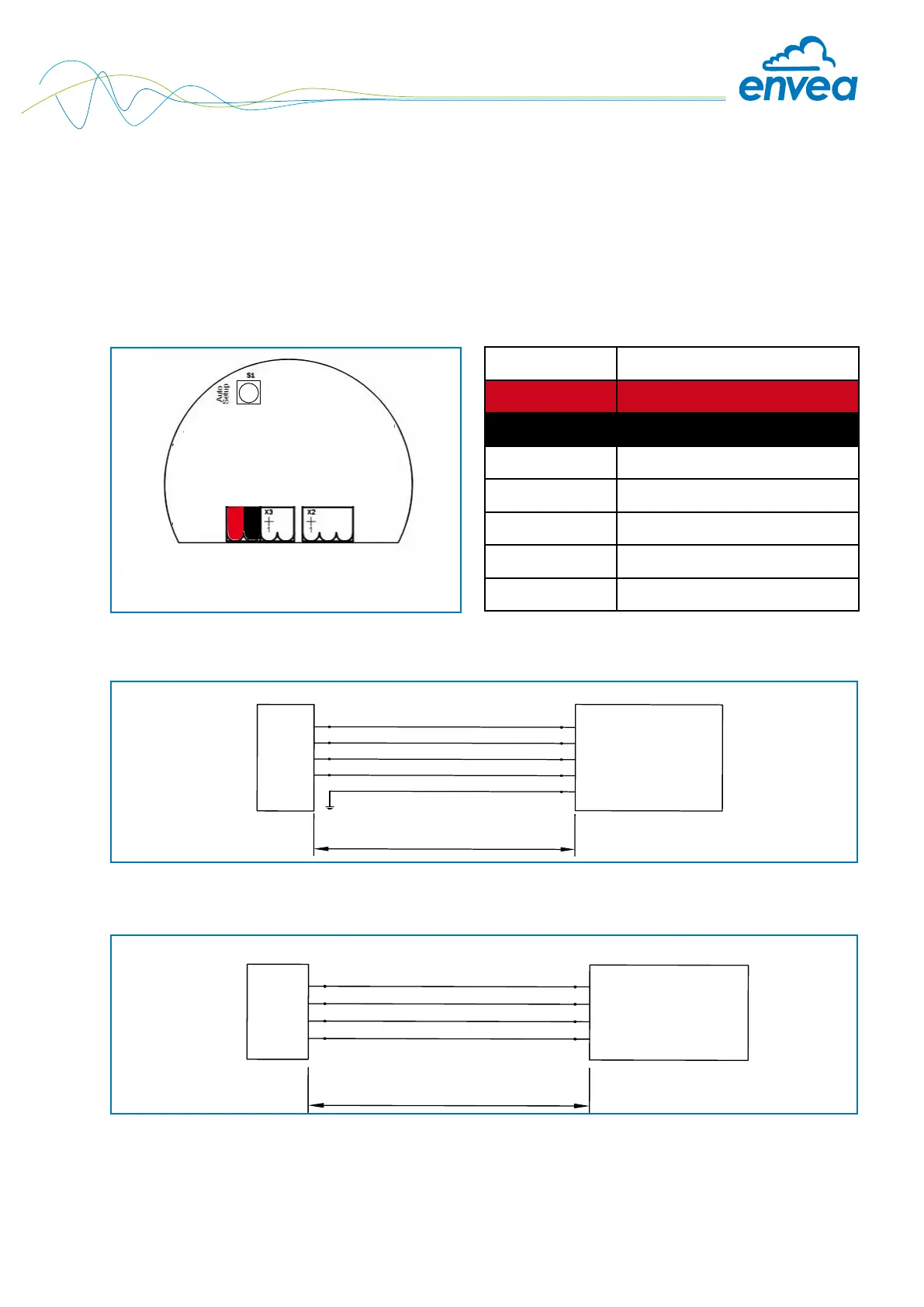
4. Electrical connection
The ProSens has an internal connection chamber with plug-in contacts which can be cabled to suit
the appropriate installation options.
Note: For EX versions cat. 1 and 2, the relay contact is only available at the Evaluation unit and not at
the sensor.
4.1 Sensor connection
Field housing connection
Sensor
PME
Max. 300 m using
wire of appropriate
cross sectional area
1
2
3
4
1 (+ 24 V)
2 (GND)
3 (A)
4 (B)
Shield
A shielded, stranded cable is recommended for long distances and environments with major
interference sources!
Sensor
DIN Rail Converter
Up to 300 m
at sufficient wire
cross section
16 (+ 24 V)
15 (GND)
14 (A)
13 (B)
1
2
3
4
DIN Rail connection
Fig. 4: Electrical connection
Tab. 1: Sensor connection
Fig. 6: DIN Rail connection
Fig. 5: Field housing connection
+ 24 V
0 V
RS 485 - A
RS 485 - B
NO
COM
NC
Contact no. Signal
1 V+ (24 V DC)
2 V- (0 V)
3 RS 485 - A
4 RS 485 - B
5 No function
6 No function
7 No function