11
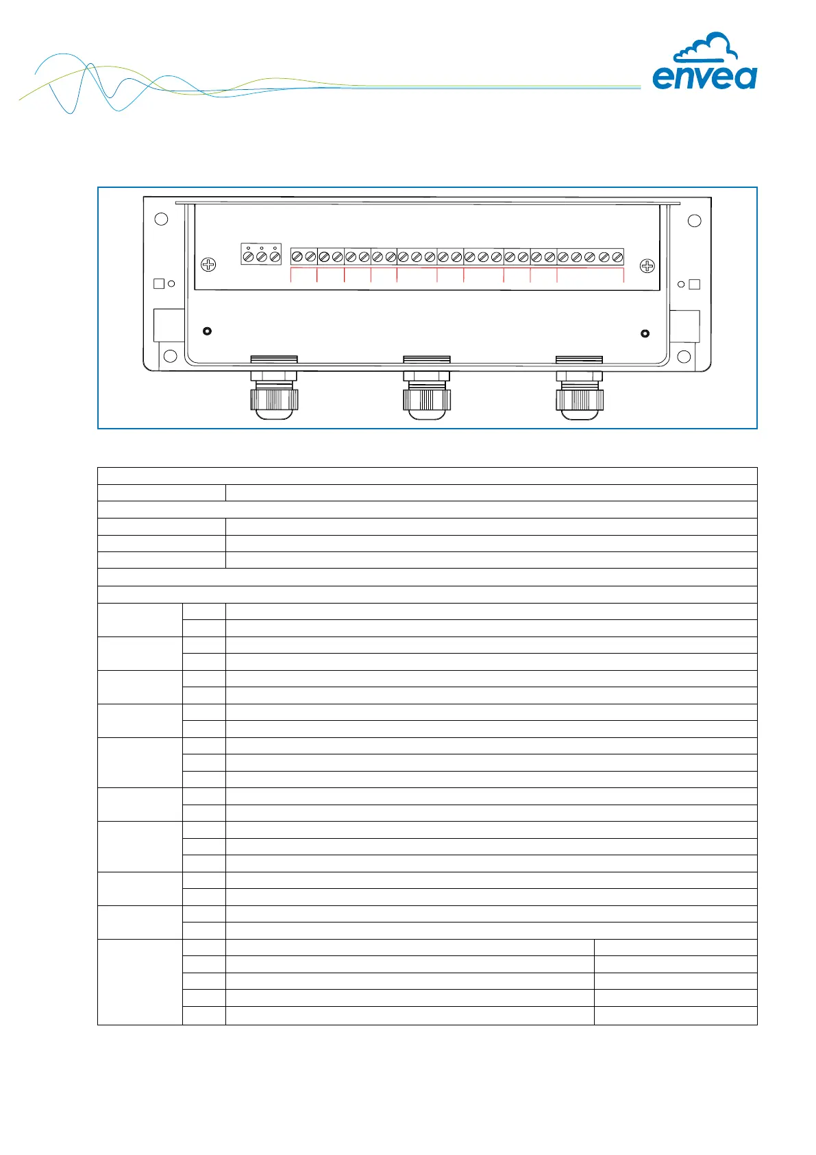
4.2 Field housing MSE 300 Evaluation unit
Fig. 7: Electrical connection
Evaluation unit
Terminal no. Connection
Power supply connection
L / +24 V Input power supply 230 V / 50 Hz, 110 V / 60 Hz (optional 24 V DC)
N / 0 V Input power supply 230 V / 50 Hz, 110 V / 60 Hz (optional 24 V DC)
PE Earth
Connections
I-in 1
+ Current input +
- Current input -
I-out 1
+ Current output +
- Current output -
I-out 2
Na Not used
Na Not used
I-out 3
Na Not used
Na Not used
Relay
NO Floating change-over contact NO (make contact)
C Floating change-over contact COM (common conductor)
NC Floating change-over contact NC (break contact)
D-out 1
Na Not used
Na Not used
RS 485
A RS 485 interface data A (+)
B RS 485 interface data B (-)
GND RS 485 interface ground
D-in 1
Na Not used
Na Not used
D-in 2
Na Not used
Na Not used
Sensor
+ Power supply 24 V (+) Cable no. 1
- Power supply 24 V (-) Cable no. 2
A RS 485 data A Cable no. 3
B RS 485 data B Cable no. 4
Shield
Shield Shield
Tab. 2: Field housing connections
L N PE
I-in 1
I-out 1
+ -
I-out 2
I-out 3
Alarm Relay
NO C NC
D-out
RS 485
A B
GND
D-in 1
D-in 2
Sensor
+ - A B
Shield
+ -
+ -
+ - + -
+ -
+ -