ENVIRO-TEC
16
FORM ET115.24-NOM11 (118)
WATER SYSTEM BALANCING
A complete knowledge of the hydronic system, its
components, and controls is essential to proper water
system balancing and this procedure should not be
attempted by unqualied personnel. The system must
be complete and all components must be in operating
condition BEFORE beginning water system balancing
operations.
Each hydronic system has different operating
characteristics depending on the devices and controls
in the system. The actual balancing technique may vary
from one system to another.
After the proper system operation is established, the
appropriate system operating conditions such as various
water temperatures and ow rates should be recorded
in a convenient place for future reference.
Before and during water system balancing, conditions
may exist which can result in noticeable water noise
or undesired valve operation due to incorrect system
pressures. After the entire system is balanced, these
conditions will not exist on properly designed systems.
CONTROLS OPERATION
Before proper control operation can be veried all other
systems must be in proper operation. The correct water
and air temperatures must be present for the control
function being tested. Some controls and features are
designed to not operate under certain conditions.
A wide range of controls and electrical options and
accessories may be used with the equipment covered
in this manual. Consult the approved unit submittals,
order acknowledgement, and other manuals for detailed
information regarding each individual unit and its
controls. Since controls and features may vary from
one unit to another, care should be taken to identify
the controls to be used on each unit and their proper
control sequence. Information provided by component
manufacturers regarding installation, operation, and
maintenance of their individual controls is available
upon request.
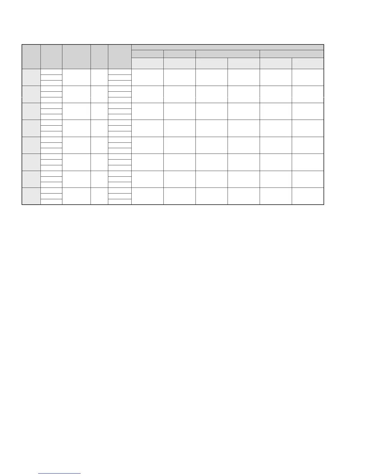
TABLE 3: EC MOTORS
UNIT
SIZE
FAN
SPEED
EC MOTOR
HP (QTY)
# OF
FANS
WATTS
2
(STD/HS)
AMPS
1,3
115 VOLTS 208/230 VOLTS 277 VOLTS
3-SPEED
(STD/HS)
2-10VDC
3-SPEED
(STD/HS)
2-10VDC
3-SPEED
(STD/HS)
2-10VDC
02
High
(1) 1/4 1
32 / 45
0.7 / 1.0 0.9 0.5 / 0.6 0.5 0.4 / 0.5 0.5Medium 21 / 36
Low 14 / 26
03
High
(1) 1/4 1
35 / 59
1.0 / 1.5 1.1 0.6 / 0.9 0.7 0.5 / 0.8 0.6Medium 23 / 43
Low 16 / 33
04
High
(1) 1/4 2
50 / 75
1.5 / 1.8 1.2 0.9 / 1.1 0.8 0.8 / 0.9 0.6Medium 33 / 56
Low 21 / 41
06
High
(1) 1/4 2
104 / 132
2.6 / 3.1 2.0 1.6 / 1.9 1.2 1.3 / 1.6 1.0Medium 62 / 89
Low 36 / 62
08
High
(1) 1/4 2
91 / 122
2.3 / 2.9 2.0 1.4 / 1.7 1.2 1.2 / 1.5 1.0Medium 54 / 90
Low 31 / 62
09
High
(1) 1/4 2
119 / 182
3.7 / 4.5 2.7 2.3 / 2.7 1.6 1.9 / 2.3 1.4Medium 72 / 116
Low 39 / 77
10
High
(2) 1/4 4
142 / 207
3.9 / 5.1 3.1 2.3 / 3.1 1.9 2.0 / 2.6 1.6Medium 91 / 139
Low 54 / 104
12
High
(2) 1/4 4
143 / 209
3.2 / 4.5 3.5 2.0 / 2.7 2.1 1.6 / 2.3 1.8Medium 92 / 152
Low 56 / 105
NOTES:
1. Motor electrical data is nameplate data.
2.WattsarebasedonanHLPwith3-speedECmotor,3rowcoil,12FPI,1"throwawaylter,0.05"ESPat115V.
3. For neutral conductor sizing, multiply AMPS by 1.73.
4. Motor data is subject to change and should not be used for submittal. Refer to unit submittal for actual ratings.
 Loading...