ENVIRO-TEC
24
FORM ET115.24-NOM11 (118)
Replacement instructions
The primary purpose of the low limit cutout is to prevent
the coil from freezing. Therefore, before mounting the
control, you need to consider all possible factors that
help protect the coil from freezing. It is important that
the cutout capillary not be cut, kinked or pinched in
mounting to unit elements. Also, ensure tubing clamps
and wells are of compatible material with the control
sensing element to prevent corrosion.
a. Disconnect the main power on the unit.
b. Locate the two inner mounting holes between
control enclosure and coil.
c. Use two supplied screws to mount the low
temperature cutout in place.
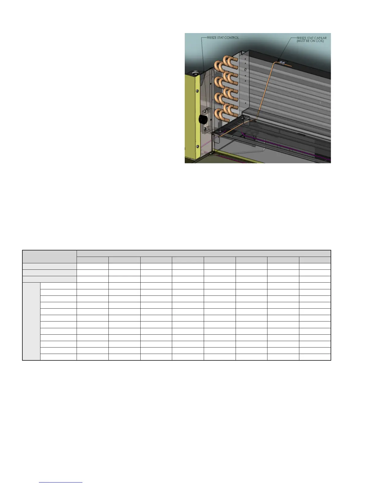
d. Work your way back up to the bellows, stringing
the sensing element throughout the drain pan,
e. Position the sensing element horizontally across
the face of the coil, and secure the sensing element
with mount tape and wire tie. (See Figure 14.)
f. Wire the NC relay using the .250 quick connectors.
g. Once all of the connections are made, reconnect
the main power of the unit.
Figure 14
TABLE 5: UNIT WEIGHT DATA (LBS./KG)
COMPONENT
UNIT SIZE
02 03 04 06 08 09 10 12
HLF BASE UNIT 22 [10] 25 [12] 33 [15] 43 [20] 53 [24] 60 [27] 74 [34] 83 [38]
HLP BASE UNIT 24 [11] 28 [13] 36 [16] 47 [21] 58 [26] 65 [30] 81 [37] 91 [41]
HLE BASE UNIT 56 [25] 63 [29] 75 [34] 92 [42] 108 [49] 118 [54] 141 [64] 158 [72]
COIL
ROWS
1 ROW - DRY 6 [3] 7 [3] 8 [4] 10 [4] 11 [5] 13 [6] 15 [7] 17 [8]
1 ROW - WET 8 [4] 9 [4] 10 [4] 12 [5] 13 [6] 15 [7] 17 [8] 19 [9]
2 ROW - DRY 7 [3] 8 [4] 10 [4] 12 [5] 14 [6] 16 [7] 19 [9] 22 [10]
2 ROW - WET 9 [4] 10 [5] 12 [5] 14 [6] 17 [8] 19 [8] 23 [10] 27 [12]
3 ROW - DRY 8 [4] 10 [4] 12 [5] 14 [6] 17 [8] 19 [9] 23 [10] 26 [12]
3 ROW - WET 10 [5] 12 [5] 15 [7] 17 [8] 21 [10] 23 [10] 28 [13] 32 [14]
4 ROW - DRY 9 [4] 11 [5] 13 [6] 17 [8] 20 [9] 22 [10] 27 [12] 30 [14]
4 ROW - WET 13 [6] 15 [7] 18 [8] 22 [10] 26 [12] 28 [13] 34 [15] 38 [17]
5 ROW - DRY 11 [5] 13 [6] 15 [7] 19 [9] 23 [10] 25 [11] 30 [14] 35 [16]
5 ROW - WET 17 [8] 19 [8] 22 [10] 26 [12] 31 [14] 33 [15] 39 [18] 45 [20]
6 ROW - DRY 12 [5] 14 [6] 17 [8] 21 [10] 26 [12] 28 [13] 34 [16] 39 [18]
6 ROW - WET 19 [9] 21 [10] 25 [11] 29 [13] 36 [16] 38 [17] 45 [21] 51 [23]
 Loading...