ENVIRO-TEC
4
FORM ET115.24-NOM11 (118)
During and after installation, special care must be taken
to prevent foreign material such as paint, plaster, and
drywall dust from being deposited in the drain pan or
on the motor or blower wheels. Failure to do so may
have serious adverse eects on unit operation and in
the case of the motor and blower assembly, may result
in immediate or premature failure. All manufacturers’
warranties are void if foreign material is allowed to be
deposited on the motor or blower wheels of any unit.
Some units and/or job conditions may require some form
of temporary covering during construction.
While the manufacturer does not become involved
in the design and selection of support methods and
components, it should be noted that unacceptable system
operating characteristics and/or performance may result
from improper or inadequate unit structural support.
In addition, adequate clearance must be provided for
service and removal of the equipment and its accessory
components. Anchoring the equipment in place is
accomplished by using the mounting points provided
and positioning the unit to maintain the unit on a LEVEL
plane. The drain pan is internally sloped toward the
outlet connection. Care must be taken to insure that
the unit drain pan does not slope away from the outlet
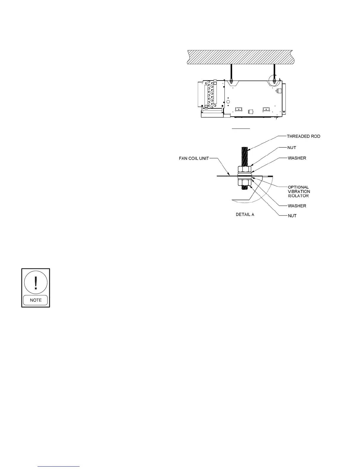
connection. All units are supplied with integrated hanger
brackets with optional grommet isolators and brass
inserts for use with 3/8" all thread hanger rod.
The unit’s drain pan is factory sloped toward the
drain connection when the unit is
installed level and plumb.
A
DETAIL A
THREADED ROD
NUT
VIBRATION ISOLATOR
NUT
WASHER
WASHER
FAN COIL UNIT
SIDE VIEW
NOTES:
1. ALL BENDS ARE 90
UNLESS OTHERWISE SPECIFIED.
2. ALL FORMED DIMENSIONS ARE OUTSIDE DIMENSIONS.
3. FEATURE QUANTITIES MAY VARY FOR DIFFERENT
CONFIGURATIONS.
TYPICAL CEILING INSTALLATION
Figure 1: Typical ceiling installation
 Loading...