ProControl User’s Manual v2.2X
7 \8100\0074_1017
2.0 ON-SITE OPERATION
2.1 LCD
Display
If your unit did not come with an LCD display, the following sections do not
apply.
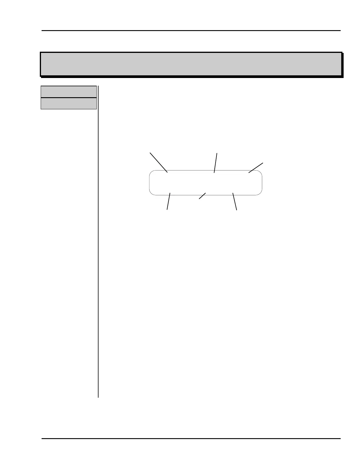
The 2 line x 20 character LCD display is used to display and control system
operations. The display is divided into separate areas or fields, as outlined below.
System Tagname
Tagname Value
Dimensional Units
or I/O Status
or Output Designation
System Status
Menu Selection
REPORT OFF
Communications
S
P
Figure 2. Display Fields
System Tagname
This six-character field is used to identify the I/O point displayed. Descriptive
names such as WELL1 or BLOWER are used.
Tagname Value
For analog inputs, this field displays the value of the input, the high alarm limit, or
the low alarm limit. For digital outputs, OUTPUT is displayed. For digital inputs,
this field is unused. For analog outputs, this field displays the output percentage,
the output level, or the associated input setpoint.
Dimensional
Units or I/O
Status
For analog inputs, this three-character field displays the dimensional units
associated with the input sensor, such as GPM or PSI. For digital inputs and
outputs, this field displays either ON or OFF. For analog outputs, this field
abbreviates percent with PCT. In the case of digital outputs, if the particular
output displayed has been designated a lamp output (see ProView manual), and a
lamp test is currently running, an asterisk (*) will appear before ON or OFF to
indicate the lamp is illuminated despite the indicated output status (the output will
return to this indicated status once the lamp test has been completed).
Menu Selection
This field displays the current menu selection.