Epson Stylus C58/C59/ME 2/C79/D78/C90/C91/C92/D92/T20/T20E/T23/T26/S20/T10/T11/ME 30/T21/T24/T27/S21 Revision E
DISASSEMBLY/ASSEMBLY Disassembling Printer Mechanism 53
Confidential
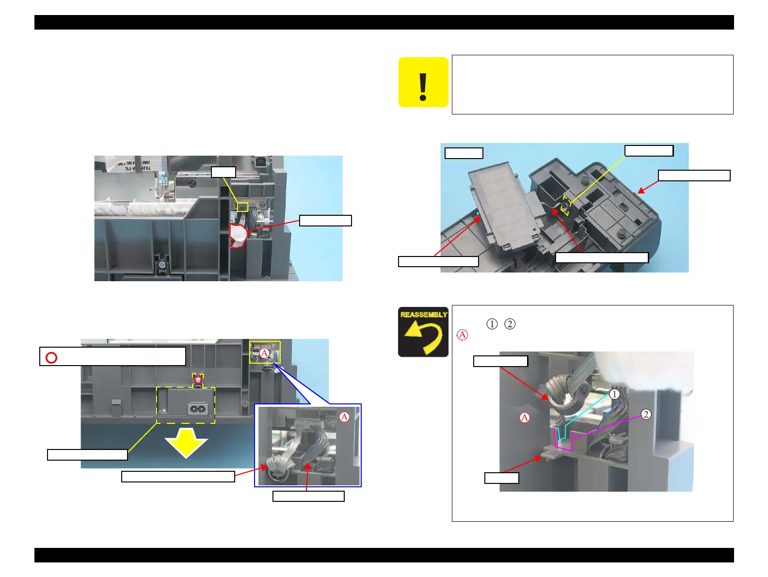
4.5.7 Power Supply Board
Part/Unit that should be removed before removing LD Roller/ASF Unit
Upper Housing
Removal procedure
1. Peel off the acetate tape from the Frame Base.
2. Disconnect the connector cable from the connector (CN8) of the Main Board.
Figure 4-44. Removing Power Supply Board (1)
3. Remove the screw (x1), and remove the Power Supply Board in the direction
of the arrow.
Figure 4-45. Removing Power Supply Board (2)
4. Pull out the connector cable through the hole of the Frame Base.
Figure 4-46. Removing Power Supply Board (3)
C.B.P 3X6 (Torque: 6±1Kgf.cm)
Power Supply Board
Cable of Power Supply Board
Cable of PF Motor
Do not turn the Power Supply Board upside down as shown in the
figure below. This figure is only used to show the location of the
parts and the harness arrangement.
When installing the Power Supply Board, arrange the cable into
the slit
, and place the ferrite core into the hook in the area
of Figure 4-45 (p.53).
Figure 4-47. Installing Power Supply Board
Power Supply Board
Hole
Connector Cable
Frame Base
Bottom