EPSON Stylus Color 440/640/740 Revision A
Chapter 7 Appendix 166
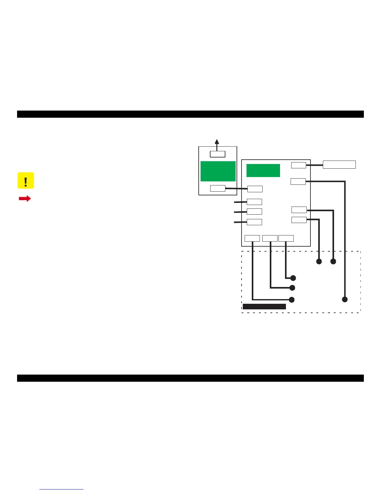
A.1.2 Connector Summary for Stylus Color 740
This section contains information on connectors in the main units of
Stylus Color 740. Figure 2 shows how the main component units of the
Stylus Color 740 are connected.
Figure A-2. Cable Connection of the Stylus Color 740
CAUTION
Information contained in this section only applies to
Stylus Color 740.
If you need information on Stylus Color 440 and Stylus
Color 640, return to Section A.1.1.
CN1
CN2
AC
CN10
CN11
CN9
C257MAIN
(Main Board)
CN1
CN2
CN7
CN8
CN6
CN4
CN5
Control Panel
Print Head
CR
Motor
PF
Motor
ASF Sensor
HP Sensor
PE Sensor
Parallel I/F
Serial I/F
Printer Mechanism
C257PSB/PSE
C257PSK
(Power Supply
Board)
CN3
USB I/F
 Loading...