EPSON Stylus Color 440/640/740 Revision A
Chapter 2 Operating Principles 56
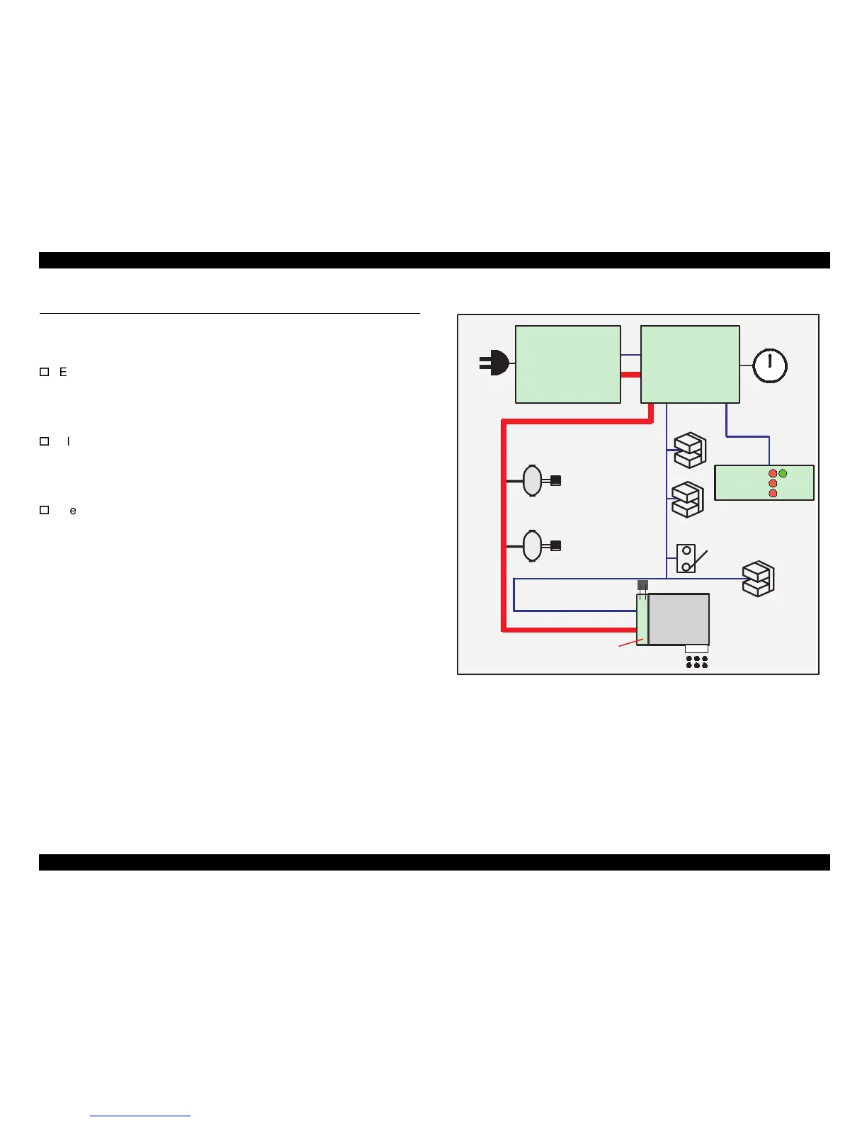
2.2 Electrical Circuit Operating Principles
Stylus Color 440/640/740 contains the following three electric circuit
boards.
Electronic Boards for Stylus Color 440 are;
Main: C206 Main-B, C255 Main Board
Power Supply: C206 PSB,PSE Board
Panel: C206 PNL Board
Electronic Boards for Stylus Color 640 are;
Main: C256 Main, Main Board
Power Supply: C206 PSB,PSE Board
Panel: C206 PNL Board
Electronic Boards for Stylus Color 740 are;
Main: C257 Main, Main Board
Power Supply: C257 PSB,PSE Board
Panel: C209 PNL Board
Refer to Figure 2-15 for the major connection of the 3 boards and their
roles.
Figure 2-15. Electric Circuit of Stylus Color 440, 640, 740
PF MOTOR
(Pump Motor)
CR Motor
C206 PSB/PSE Board
C257 PSB/PSE Board
+5 V DC
AC Input
INK END counter
and P-off time
counter
PE Sensor
BCO/CCO Sensor
ASF Lever
Position Sensor
Print Head
+42 V DC
Head Drive Board
CRHP Sensor
Thermistor
12
6
3
9
1
2
4
57
8
10
11
C206 Main-B
C255 Main
C256 Main
C257 Main
+5 V DC
+42 V DC
C206 PNL
C209 PNL
LED
+5 V DC
 Loading...