EPSON Stylus Color 440/640/740 Revision A
Chapter 2 Operating Principles 60
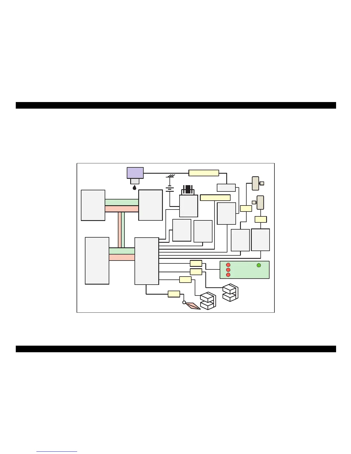
2.2.2 C206 Main-B, C255 Main (for Stylus Color 440)
Various DC voltage generated on the C206 PSB/PSE board is added
various signals in order to drive the printer function on the C206 main-B,
C255 main, board the drive of CR/PF (Pump) motor and printing head is
performed. Following figure shows the circuit diagram for Stylus Color
440.
Figure 2-17.
C206 Main-B, C255 Main Board Block for Stylus Color 440
TPM95C061
(IC1)
P-ROM
(IC3)
Address
Data
Address
Data
Reset IC
(IC9)
CR1
Timer
Counter
(IC5)
Batt1
EEPROM
(IC11)
CN1 Parallel
Common
Driver
(IC6)
Q7&Q9
Head
CN8 HD FFC
Motor
Driver
(IC14)
Motor
Driver
(IC15)
PF Motor
CR Motor
CN6
CN7
C206 PNL
CN3
CN11
ASF Sensor
CN5
HP Sensor
CN4
PE Sensor
E05B44
(IC2)
D-RAM
(IC4)
 Loading...