EPSON Stylus Color 440/640/740 Revision A
Chapter 2 Operating Principles 64
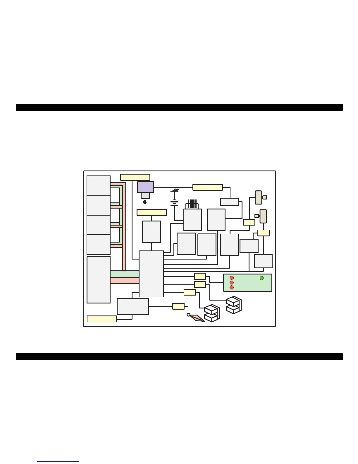
2.2.4 C257 Main, (for Stylus Color 740)
Various DC voltage generated on the C257 PSB/PSE board is added
various signals in order to drive the printer function on the C257 main
board the drive of CR/PF (Pump) motor and printing head is performed.
Following figure shows the circuit diagram for Stylus Color 740.
Figure 2-19. C257 Main Board Block for Stylus Color 740
Address
Data
Reset IC
(IC9)
CR1
Timer
Counter
(IC8)
Batt1
EEPROM
(IC7)
CN1 Parallel
Q2&Q3
Head
CN9 HD FFC
PF Motor
CR Motor
CN7
C209 PNL
CN11
CN6
ASF Sensor
CN4
HP Sensor
CN5
PE Sensor
Transceiver
(IC10)
CN2 Serial
Motor
Driver
(IC13)
Common
Driver
(IC14)
CN8
Motor
Driver
(IC12)
Buffer
(IC9)
CN3 USB
P-ROM
(IC3)
D-RAM
(IC4)
M-ROM
(IC6)
D-RAM
(IC5)
Motor
Driver
(IC11)
C90A05
(IC1)
E05B588
(IC2)
 Loading...