2. Installation
64 Safety and Installation (T, VT / EPSON RC+ 7.0) Rev.15
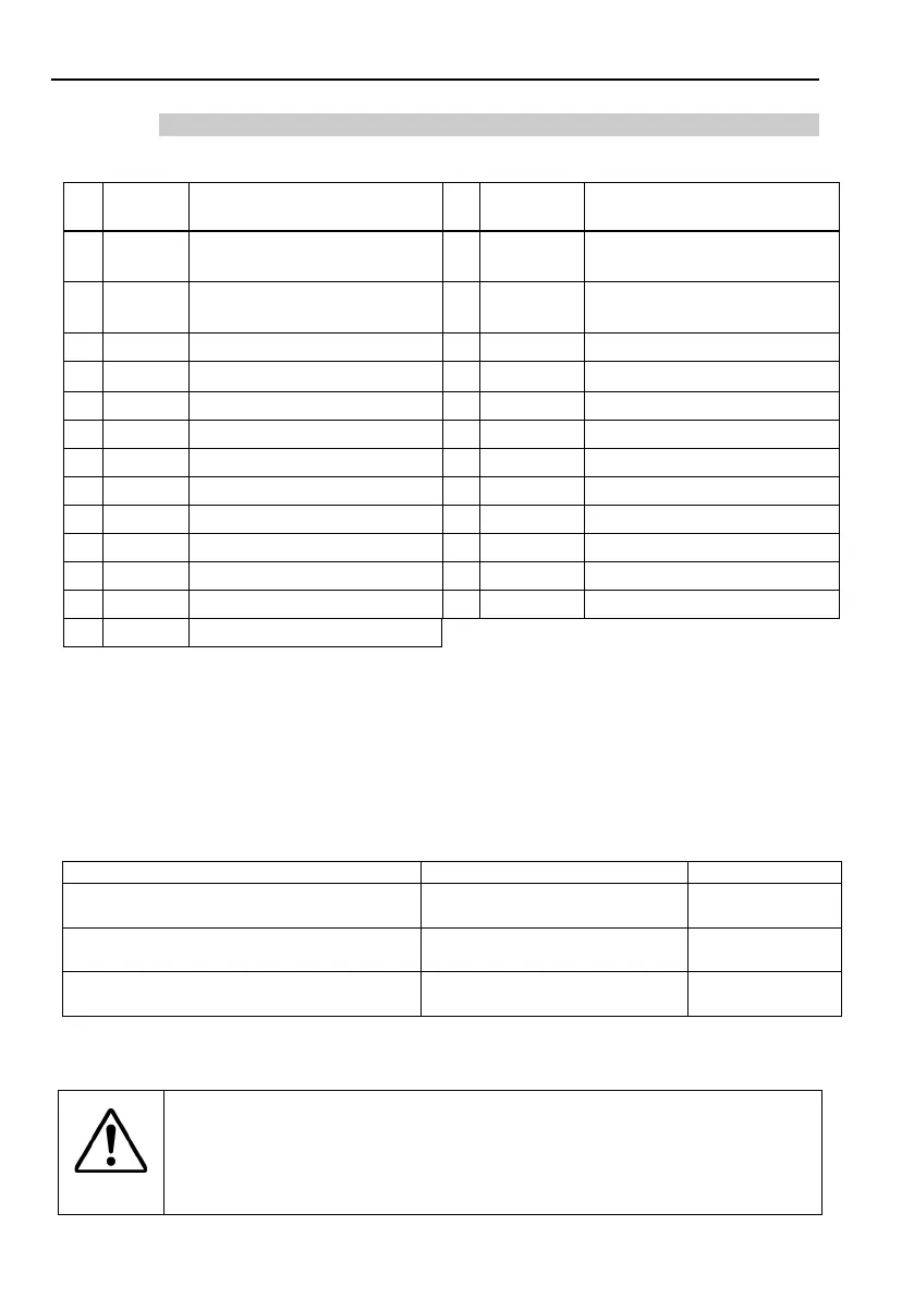
2.5.7 Pin Assignments
The EMERGENCY connector pin assignments are as follows:
(D-Sub 25 pin male)
Signal Function
Signal Function
1 ESW11
Emergency Stop switch
*3
14 ESW21
Emergency Stop switch
*3
2 ESW12
contact (1)
*3
15 ESW22
contact (2)
*3
Emergency Stop circuit 1 (+)
*4
Emergency Stop circuit 2 (+)
*4
4
ESTOP1
Emergency Stop circuit 1 (-)
*4
17
ESTOP2−
Emergency Stop circuit 2 (-)
*4
Safety Door Latch Release
Safety Door Latch Release
*1 Do not connect anything to these pins.
*2 A critical error occurs if the input values from the Safety Door 1 and Safety Door 2 are different
for two or more seconds. They must be connected to the same switch with two sets of
contacts.
*3 A critical error occurs if the input values from the Emergency Stop switch contact 1 and
Emergency Stop switch contact 2 are different for two or more seconds. They must be
connected the same switch with two sets of contacts.
*4 Do not apply reverse voltage to the Emergency Stop circuit.
Emergency Stop switch output rated load
Emergency Stop rated input voltage range
Emergency Stop rated input current
+24 V ±10%
37.5 mA ±10% / +24V input
3-4, 16-17 pin
Safety Door rated input voltage range
Safety Door rated input current
+24 V ±10%
10 mA / +24 V input
7-8, 20-21 pin
Latch Release rated input voltage range
Latch Release rated input current
+24 V ±10%
10 mA / +24 V input
18-19 pin
The total electrical resistance of the Emergency Stop switches and their circuit should
be 1 Ω or less.
CAUTION
■
The 24 V output is for emergency stop. Do not use it for other
purposes. Doing so may result in system malfunction.
■
Do not apply reverse voltage to the Emergency Stop circuit.
Doing so may result in system malfunction.
NOTE

 Loading...


