Epson WF-7520/7510/7010 series Revision A
Disassembly/Reassembly Detailed Disassembly/Reassembly Procedure for each Part/Unit 59
Paper Stopper Assy 1st / 2nd (1)
If any of the parts of the Paper Stopper Assy 1st/2nd comes off
when removing it, be sure to reassemble the Paper Stopper Assy
1st/2nd as shown above.
Paper Stopper
Compression Spring 0.9
Compression Spring 0.787
Secure springs (x4) with dowels.
Slider Base
Cam Slider
Slider Cassette
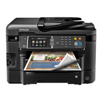
Paper Stopper Assy 1st / 2nd (2)
Tighten the screws in the order indicated in the figure above.
C.B.S-TITE SCREW 3x8 F/ZN-3C (6 ± 1 kgf·cm)
1
2
Paper Stopper Assy 1st
Paper Guide Stopper Assy 1st
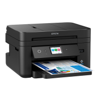
WF-7520/7510/7010 series
C.B.S-TITE SCREW 3x8 F/ZN-3C (8 ± 1 kgf·cm)
1
2
Paper Guide Stopper Assy 2nd
Paper Stopper Assy 2nd
WF-7520/7010 series
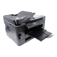
Paper Guide Stopper Assy 1st
When installing the Paper Guide Stopper Assy 1st, align the
dowels (x4) of the Frame Base Assy with the positioning holes (x4)
of the Paper Guide Stopper Assy 1st, and then tighten the screws in
the order indicated in the figure above.
C.B.P-TITE SCREW 3x10 F/ZN-3C (6 ± 1 kgf·cm)
1
2
3
4
Frame Base Assy
Dowel and positioning hole
Paper Guide Stopper Assy 1st
Paper Guide Stopper Assy 2nd
(WF-7520/7010 series)
When installing the Paper Guide Stopper Assy 2nd, align the
dowels (x4) of the 2nd Bin Base Assy with the positioning holes
(x4) of the Paper Guide Stopper Assy 2nd, and then tighten the
screws in the order indicated in the figure above.
C.B.P-TITE SCREW 3x10 F/ZN-3C (6 ± 1 kgf·cm)
1
2
3
4
2nd Bin Base Assy
Paper Guide Stopper Assy 2nd
Dowel and positioning hole
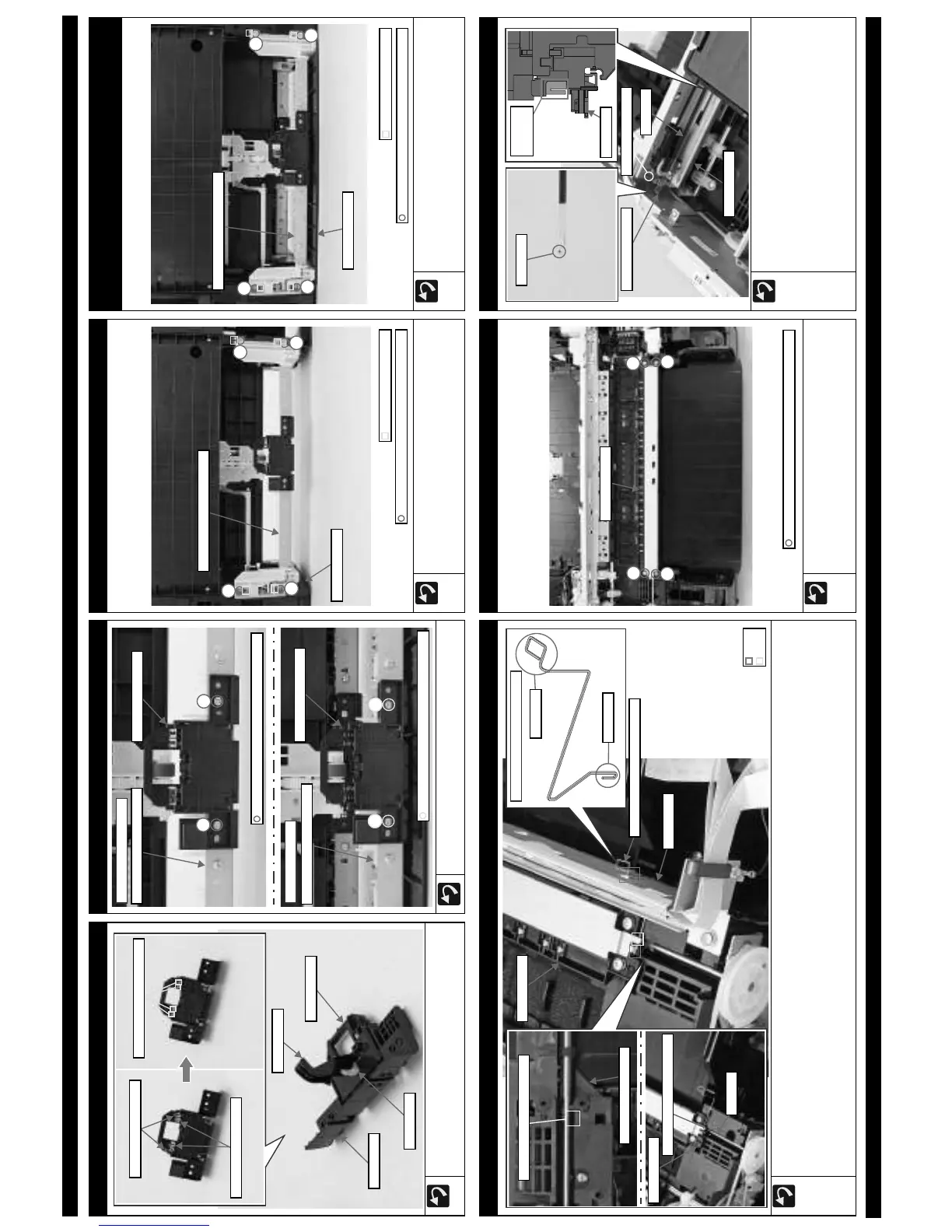
HS Support Plate Grounding Spring
When attaching the HS Support Plate Grounding Spring, follow the procedure below.
1. Insert the spring leg A of the HS Support Plate Grounding Spring into the hole of the Paper Guide Front Assy.
2. Route the HS Support Plate Grounding Spring through the hook then under the rib of the Star Wheel Assy, and install the Star Wheel Assy to the
Paper Guide Front Assy.
(p 59)
3. Install the Front Frame Assy. (p 60)
4. Engage the spring leg B of the HS Support Plate Grounding Spring onto the hook of the Front Frame Assy. After installation, confirm the HS
Support Plate Grounding Spring touches the EJ Roller Shaft.
Hole of Paper Guide Front Assy
Paper Guide Front Assy
EJ Roller
Make the spring touch EJ Roller
Star Wheel Assy
HS Support Plate Grounding Spring
Spring leg A
Spring leg B
HS Support Plate Grounding Spring
Hook
Rib
Front Frame
Star Wheel Assy
Star Wheel Assy
Before installing the Star Wheel Assy, attach the HS Support
Plate Grounding Spring to the hook of the Star Wheel Assy.
(p 59)
Tighten the screws in the order indicated in the figure above.
1
2
3
4
C.B.P-TITE (S-P1) SCREW 3x12 F/ZN-3C (6 ± 1 kgf·cm)
Star Wheel Assy
CR Scale / Torsion Spring 7.13
Install the CR Scale with the black mark section on the top left.
Make sure to put the CR Scale through the slit of the CR Encoder.
When attaching the Torsion Spring 7.13, follow the procedure below.
1. Attach the Torsion Spring 7.13 to the CR Guide Plate, and hook
the shorter leg of the Torsion Spring 7.13 on the CR Scale.
2. Hook the longer leg of the Torsion Spring 7.13 to the
cutout of the Main Frame to complete the Torsion Spring
7.13 attachment.
Slit of CR
Encoder
CR Unit
Black mark
CR Scale
Torsion Spring 7.13 Cutout of Main Frame
CR Guide Plate