Epson WF-7520/7510/7010 series Revision A
Disassembly/Reassembly Routing FFCs/cables 64
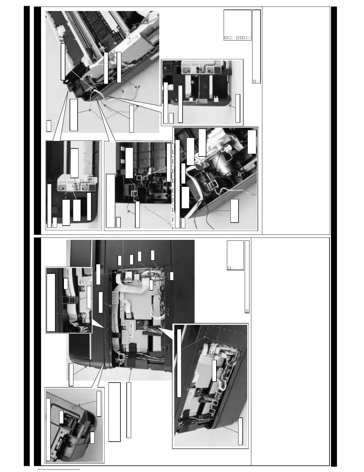
Inside the USB Cover (ADF Unit/Scanner Unit related cables: WF-7520/7510 series)
For the correspondence between the cables, FFCs and the connectors on the Main Board, see “ Main Board Unit (2) (p65)”.
When routing the Scanner Motor cable (CN2), ADF PE Sensor cable (CN18), ADF Encoder cable (CN19), ADF Document Sensor cable (CN22), ADF
Motor cable (CN24), ADF grounding wire and scanner grounding wire, follow the procedure below.
1. Insert all cables into the hole of the Housing Upper, and then route them under the rib A.
2. Secure the ADF grounding wire and scanner grounding wire together on the position shown above with the screw.
3. Route the Scanner Motor cable (CN2), ADF PE Sensor cable (CN18), ADF Encoder cable (CN19), ADF Document Sensor cable (CN22) and ADF Motor
cable (CN24) through the hook of the Frame Base Assy and route them inside the rib B (x8), and then connect them to the connectors on the Main Board.
4. Put the ferrite core A of the ADF Motor cable into the position shown above.
5. Insert the excess portions of the Scanner Motor cable, ADF PE Sensor cable, ADF Encoder cable, ADF Document Sensor cable and ADF Motor cable
into the space between the Housing Upper and Main Board.
6. Secure the Scanner Motor cable, ADF PE Sensor cable, ADF Encoder cable, ADF Document Sensor cable, ADF Motor cable, ADF grounding wire and
scanner grounding wire on the positions shown above with acetate tape.
When routing the Scanner FFC, follow the procedure below.
1. Insert it into the hole B of the Housing Upper, and route under the rib A of the Housing Upper.
2. Route the Scanner FFC through the ferrite core B and insert the ferrite core B into the inside of the rib C of the Housing Upper, and then secure it with double-sided tape.
3. Secure the Scanner FFC on the position shown above with double-side tape, and then connect the FFC to the connector (CN41) on the Main Board.
Hole A
Hole B
Housing Upper
Top: Before ADF / Scanner Unit is installed
Frame Base Assy
Space between Housing Upper and Main Board
Ferrite core A
Hook
Rib A
Double-sided tape
C.B.S-TITE SCREW 3x6 F/ZN-3C (6 ± 1 kgf·cm)
Scanner FFC
Secure ADF grounding wire and Scanner
grounding wire together with the screw.
Ferrite core B
Rib C
Rib B
Main Board
Scanner Unit
Insert all cables/FFCs of ADF Unit and
Scanner Unit into hole of Housing Upper,
and then route them under rib A.
CN22
CN41
CN19
CN18
CN2
CN24
Secure with acetate tape (20 x 65 mm).
2nd Bin Base Assy (WF-7520/7010 series)
When routing the Paper Stopper Lever Sensor 2nd cable and grounding wire A, follow the procedure below.
1. Route the Paper Stopper Lever Sensor 2nd cable and grounding wire A through the groove 1 (x3) of the Paper Guide Stopper Assy 2nd and through the
hook A, and then insert them into the hole on the bottom of the 2nd Bin Base Assy.
(See Fig. 2.)
2. Pull out the Paper Stopper Lever Sensor 2nd cable and grounding wire A from the hole on the upper side of the 2nd Bin Base Assy, and route them as
follows.
(See Fig. 3.)
• Grounding wire A Route it through the hook B and hook C of the 2nd Bin Base Assy.
• Paper Stopper Lever Sensor 2nd cable Route it through the hook B of the 2nd Bin Base Assy, and then make one turn around the hook C.
3. Install the Frame Pickup Assy to the 2nd Bin Base Assy, and secure the grounding wire A to the Frame Pickup Assy with the screw (x1).
(See Fig. 4.)
Route the Pickup Motor cable, Pickup Encoder FFC and grounding wire B as follows. (See Fig. 4.)
• Pickup Motor cable Route it through the hook C and groove 2, and put the ferrite core of it into the position shown above. Then, route the cable
through the groove 3 and route it through the hook C once again.
• Pickup Encoder FFC Secure it on the position shown above with double-sided tape.
• Grounding wire B Secure it on the Frame Pickup Assy with the screw, and route it through the hook C.
Insert the Paper Stopper Lever Sensor 2nd cable, Pickup Motor cable, Pickup Encoder FFC and grounding wire B into the hole on the bottom of the Frame
Base Assy, and pull them out from the upper side of the Frame Base Assy.
(See Fig. 1, Fig. 5.)
Paper Stopper Lever
Sensor 2nd cable
Grounding wire A
Hole of 2nd Bin Base Assy
Top of 2nd Bin Base Assy:
Before Frame Pickup Assy is installed
Fig. 3
Bottom of 2nd Bin Base Assy
Paper Stopper Lever
Sensor 2nd cable
Grounding wire A
Hole of 2nd
Bin Base Assy
Paper Guide
Stopper Assy 2nd
Fig. 2
Hole of Frame Base Assy
Paper Stopper Lever
Sensor 2nd cable
Pickup Encoder FFC
Pickup Motor cable
Grounding wire B
C.B.P-TITE SCREW 3x8 F/ZN-3C (6 ± 1 kgf·cm)
C.B.S-TITE SCREW 3x6 F/ZN-3C (6 ± 1 kgf·cm)
Bottom of Frame Base Assy
Hole of Frame Base Assy
Fig. 5
Frame Base Assy
Top of 2nd Bin Base Assy: After Frame Pickup Assy is installed
Screw to secure
grounding wire B
Frame Pickup
Assy
Fig. 4
Pickup Motor
cable
Ferrite core
Pickup
Encoder FFC
Screw to secure
grounding wire A
Hook A
Hook B
Groove 2
Hook C
Groove 3
Groove 1