FR
ES
PT
IT
EL
PL
RU
KZ
UA
RO
EN
123
F
A
C
E
D
G
4
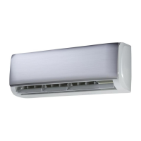
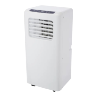
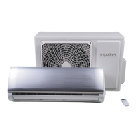
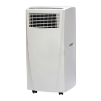
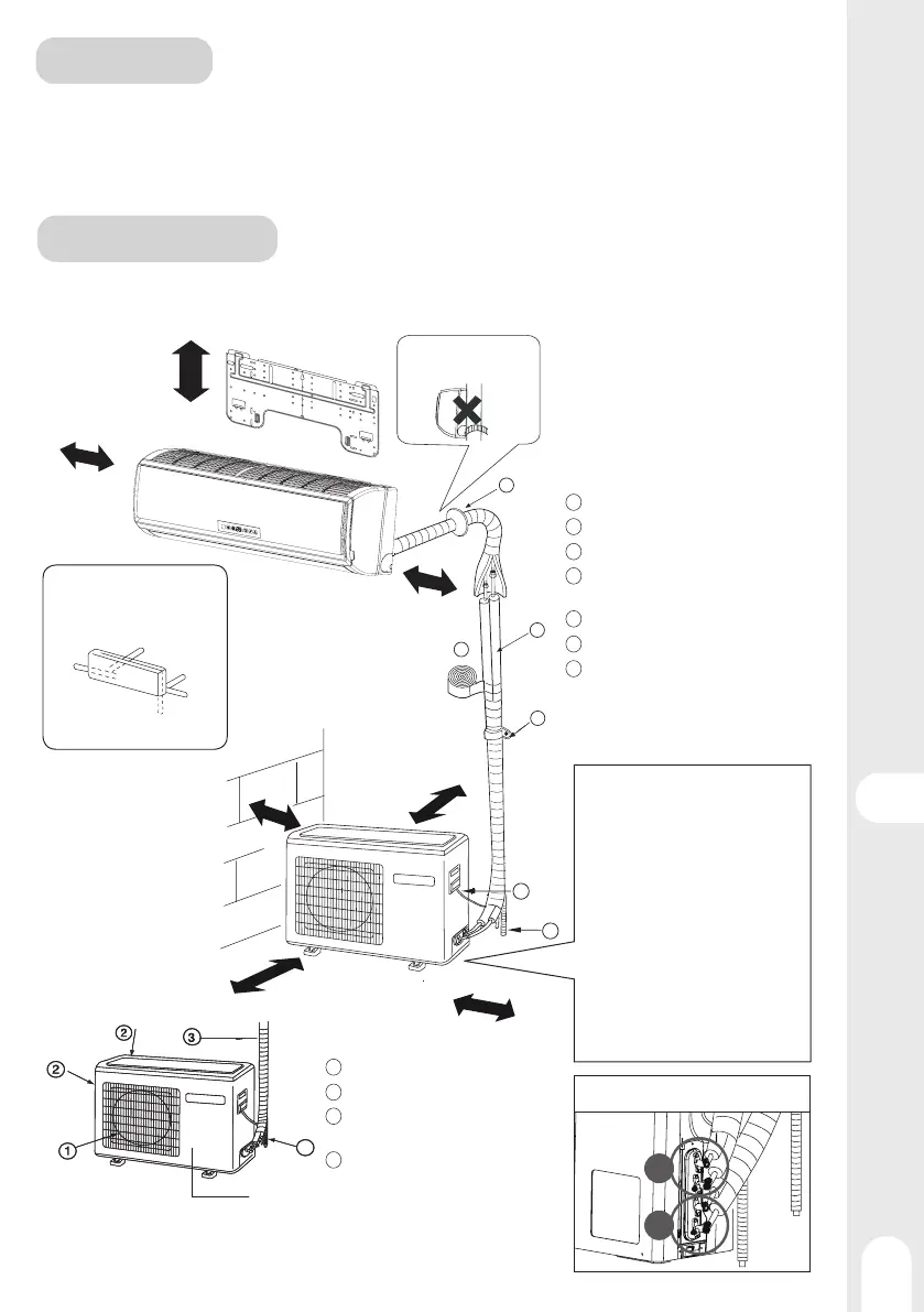
INSTALLATION
Indoor/Outdoor Unit Installation Drawings
• The models adopt HFC refrigerant R32.
WARNING
• Please read the instructions of both manuals before installing and using the unit.
• Legal instructions are located at the beginning of user manual.
• For detailed technical informations, please read the supplied Product Fiche, and
consult http://www.erp-equation.com/ac/
more than 15cm
more than 10 cm
more than 10 cm
more than
20 cm
more than 20 cm
more than 60 cm
Compressor (Inside of Unit)
more than 25 cm
Arrangement of piping
directions
Rear left
Rear
right
Right
Left
Below
1 Air outlet
2 Air inlet
3 Connecting piping and electrical
wiring
4 Drin hose
Optional parts for piping
A Non-adhesive tape
B Adhesive tape
C Saddle (L.S) with screws
D Connecting electric cable for indoor
and outdoor
E Drain hose
F Heating insulating material
G Piping hole cover
Attention must be paid to
the rising up of drain hose
• The marks from A to G in
the figure are the parts
numbers.
• The distance between
the indoor unit and the
floor should be more
than 2m.
Fixing of outdoor unit
• Fix the unit to concrete or block
with bolts (10mm) and nuts fir-
mly and horizontally.
• When fitting the unit to wall sur-
face, roof or rooftop, fix a suppor-
ter surely with nails or wires in
consideration of earthquake and
strong wind
• If vibration may aect the house,
fix the unit by attaching a vibra-
tion-proof mat.
• If using the left side drain pipe, make sure the hole is got through.
• The above indoor and outdoor units’ picture is just for your reference.
• Please be subject to the actual product purchased.
A
B
Bi-split connection