41 / 42
6 • Maintenance and servicing
80116-221
10.15
Test procedure for VIO 100 C
1. Set the test specimen to:
BIPOLAR (=BIPOLAR SOFT COAG), 80 Watt
2. Set HF power meter to:
RL = 100 Ohm
3. Activate test specimen via COAG pedal on the footswitch.
4. Determine and document the measured value. The tolerance range is
64 to 96 watts.
Monitor circuits
NE monitoring of critical resis-
tance
for
dual surfaced
return electrodes
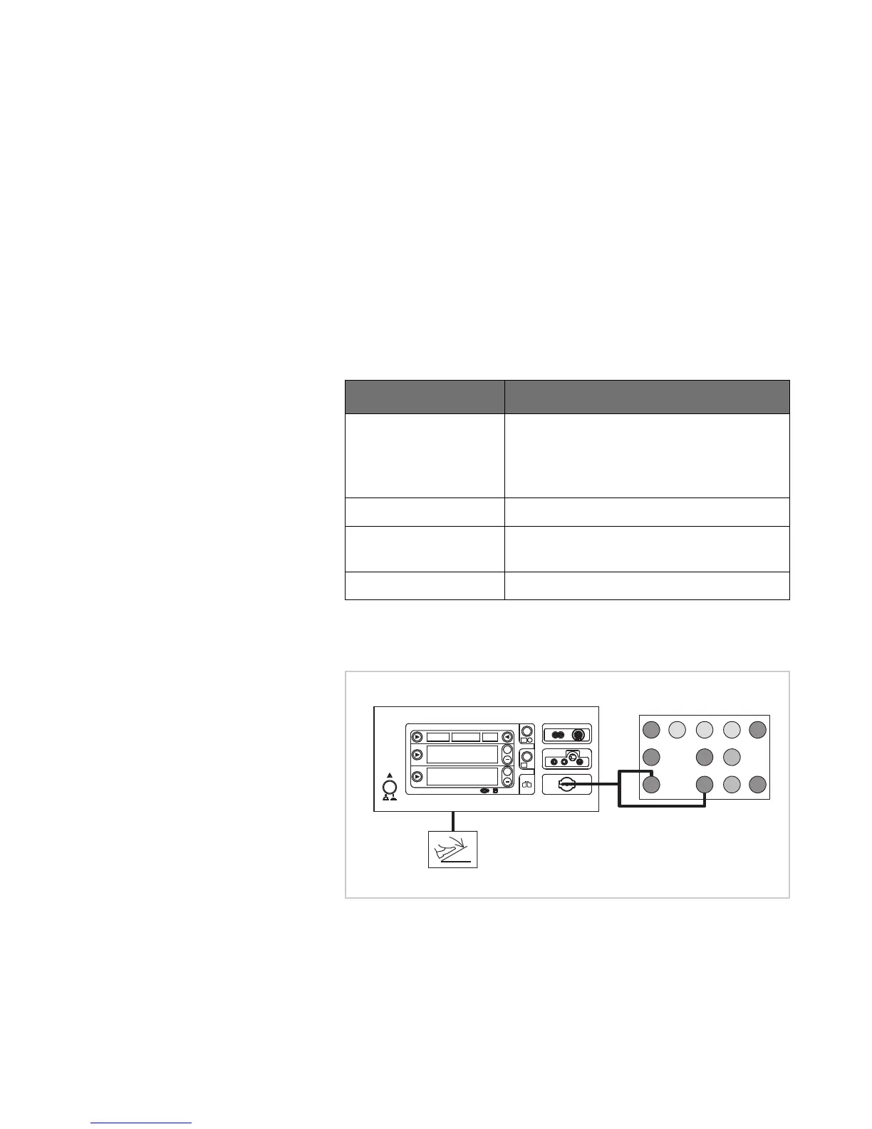
Testing and measuring equipment
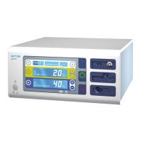
Test set-up and test procedure
1st test step
Fig. 6-6
• The test specimen is connected to the power supply via the power
cord.
• The test is performed without a load.
• The NE receptacle of the test specimen is connected to the VIO Testbox
via the patient cable NE with the adapter cable.
• The dual-pedal footswitch is connected.
Erbe Art. No. Description
20194-070 Patient cable NE
or
Patient cable NE, international
20194-075
20100-033 Adapter cable NE
20100-101 VIO Testbox Symmetry/Resistance (NE
asymmetry/critical resistance)
20189-107 Two pedal footswitch VIO C