BPage12 BEA--220265-EN-04
CCDarraycameraOptoLineOL80..
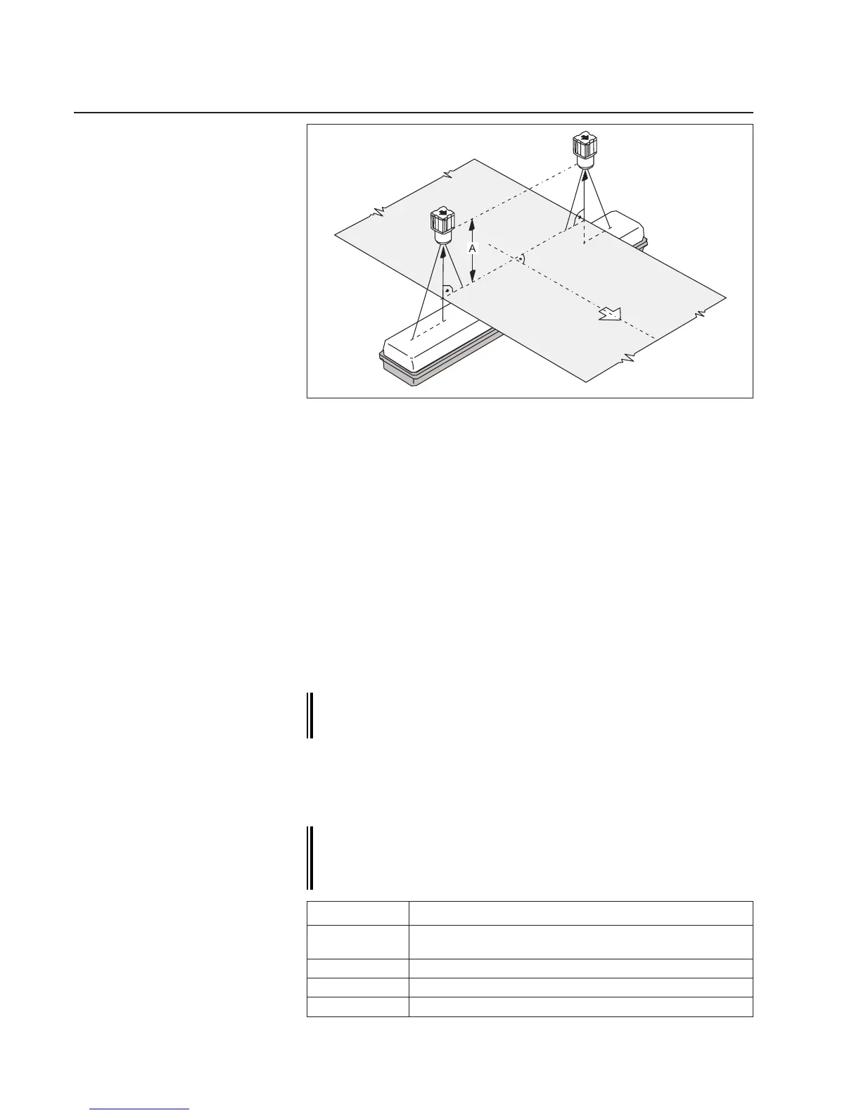
➜Setthecameravisualrange(CCDarray)ata90°angletothe
websurfaceandwebcenter.Ensurewhenmeasuringwithtwo
cameras,thatbotharesetatthesamedistanceAfromtheweb.
➜Forfrontlighting,alignthecameraandlighttransmitterwithone
another(seeillustrationontopofpage10).
➜Seewiringdiagram.
➜Seewiringdiagram.
ThecamerahasaCANaddressbywhichitcanbereachedviathe
bus.TheCANaddressconsistsofagroupanddevicenumber.The
(Group)numberreferstowhichcontrolloopthedevicebelongs,the
(Device)numbertothespecicdeviceinthecontrolloop.
On systems designed by E+L the CAN address is works set.
The CAN address is specied on the type plate along with the
module reference and is listed in the system block diagram.
Ifcamerasaresuppliedindividually,asacomponentofsystemsnot
designedbyE+L,youmustsettheCANaddress.Todoso,seethe
"CANbus,serialbusandsetupeditor"description.Inthiscase,cam-
erasaresuppliedwithCANaddress0.1.
The camera device numbers are xed, see table below. The
device numbers specify the mounting location (to the right or
left in the direction of web travel) and thus the camera edge
scanning direction.
7.2 Check wiring Check wiring
7.3 Check supply voltage
7.4 Set camera CAN address
7.1 Position camera
Example:Backlighting
Devicenumber Sensorindirectionofwebtravel
1 -cameraonright
-onlyonecameraoverwebcenter
2 -cameraonleft
3 -secondcameraonright(forspecialapplications)
4 -secondcameraonleft(forspecialapplications)