BPage6 BEA--220265-EN-04
CCDarraycameraOptoLineOL80..
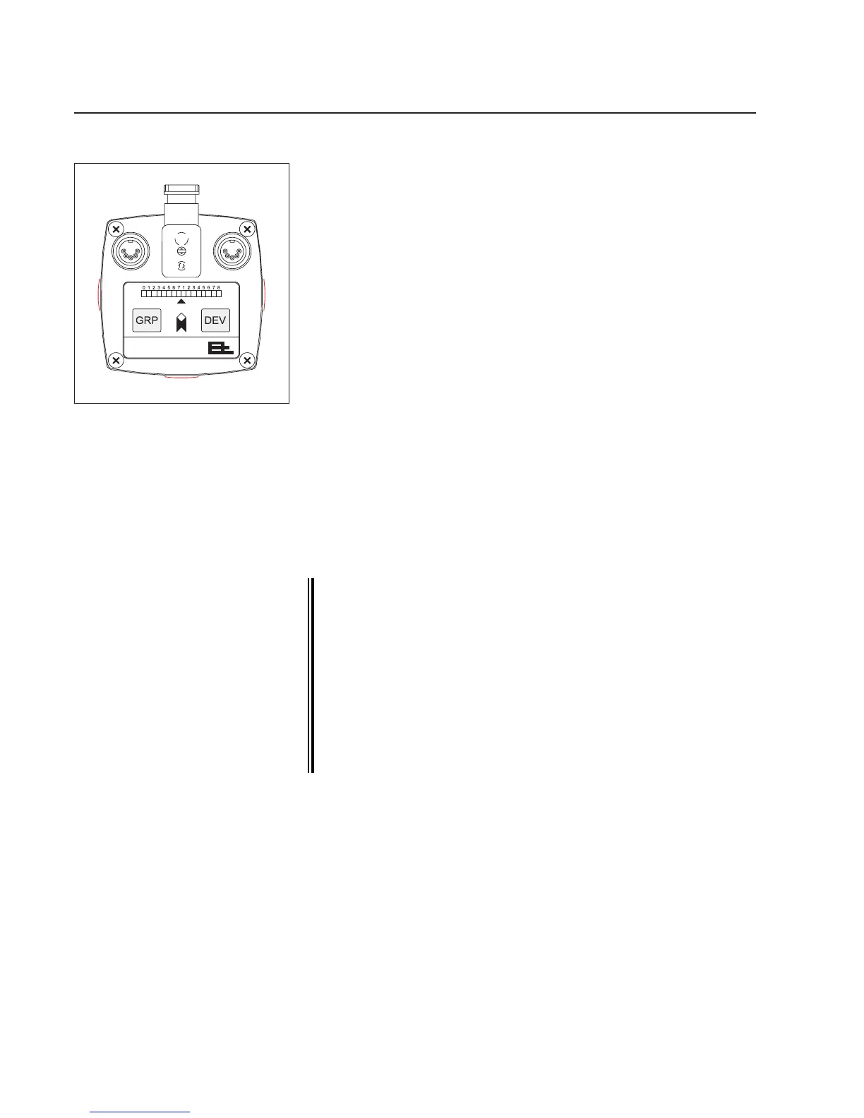
4. Camera controls
LED display
Innormalmode,theLEDdisplayindicatesthepositionofthemea-
suredvalue(e.g.thewebcenter)inthecamerameasuringrange.In
theeventofmalfunctions,itindicatesvariouserrors,seeerrormes-
sagessection.
Arrow
TheLEDonthearrowindicateswhenthecameraisreadyforop-
eration.Whenconnectedtothepower,itlightsupreduntilcamera
initializationiscomplete.Whenthecameraisreadyforoperationit
lightsupgreen.
GRP key
UsetheGRPkeytosetthegroupnumberandfocusthecamera,see
the"SettingthecameraCANaddress"and"Focusingthecamera"
sections.
DEV key
UsetheDEVkeytosetthecameradevicenumber,see"Settingthe
cameraCANaddress"section.
TheDEVkeyisalsousedtosetwhichmeasuredvalueistobein-
dicatedontheLEDdisplay.PressandholddowntheDEVkey.The
addressofthemeasuredvaluecurrentlybeingdisplayedisindicated.
Theaddressesofallconguredmeasuredvaluesaredisplayedin
sequenceat5secondintervals.Releasethekeyoncetheaddressof
therequiredmeasuredvalueappears.
Other settings by the E+L Setup Editor.
The setup editor is a software tool for calibrating and con-
guring E+L CAN modules such as camera OL 80.. . In setup
mode parameters can be displayed and some changed as
well. Setup mode is accessed via a command station DO ....
or operator panel RT .... . See description "CAN-Bus, serial
bus and setup editor".
If the cameras are used only for width measuring, i.e. the
system only has a remote display DO 002. (no E+L controller
DC..), the device number of the remote display must always
be 5 (device 5). Only then can the setup editor be started.
Cameracontrols