BPage20 BEA--220265-EN-04
CCDarraycameraOptoLineOL80..
7.8 Camera calibration
7.7.3 Conguring the 3rd to 8th measured values:
Proceed as for conguring the 2nd measured value for all fur-
ther measured values that are to be output.
First enter the camera CAN address, then set one sub ad-
dress (parameters 48 to 53) and initiate a reset. Finally, set
the operating mode of the new measured value.
7.7.4 Deactivating the output of measured values:
➜Callupsetupeditor
➜Enterthecameradevicenumberinparameter0.
1 for the camera
➜Enterthecameragroupnumberinparameter1.
0 for the camera
➜Setthesubaddress(parameters47to53)ofthemeasuredvalue
thatistobedeactivatedto00.
0.0 in parameter 47 for the second measured value
➜Entera1(reset)inparameter3,thenchangeparameterstoiniti-
atethereset.
Toachieveauniformreferencevariableforcontrolormeasuring
systemsignals,allsensorsandactuatorsmustbecalibratedinrela-
tiontothisuniformreferencevariable.
Therearetwodifferentcalibrationproceduresforthecamera,
standardcalibrationandtemplatecalibration.Thelatterisintend-
edforcamerasimplementedinlaminationprocesses.
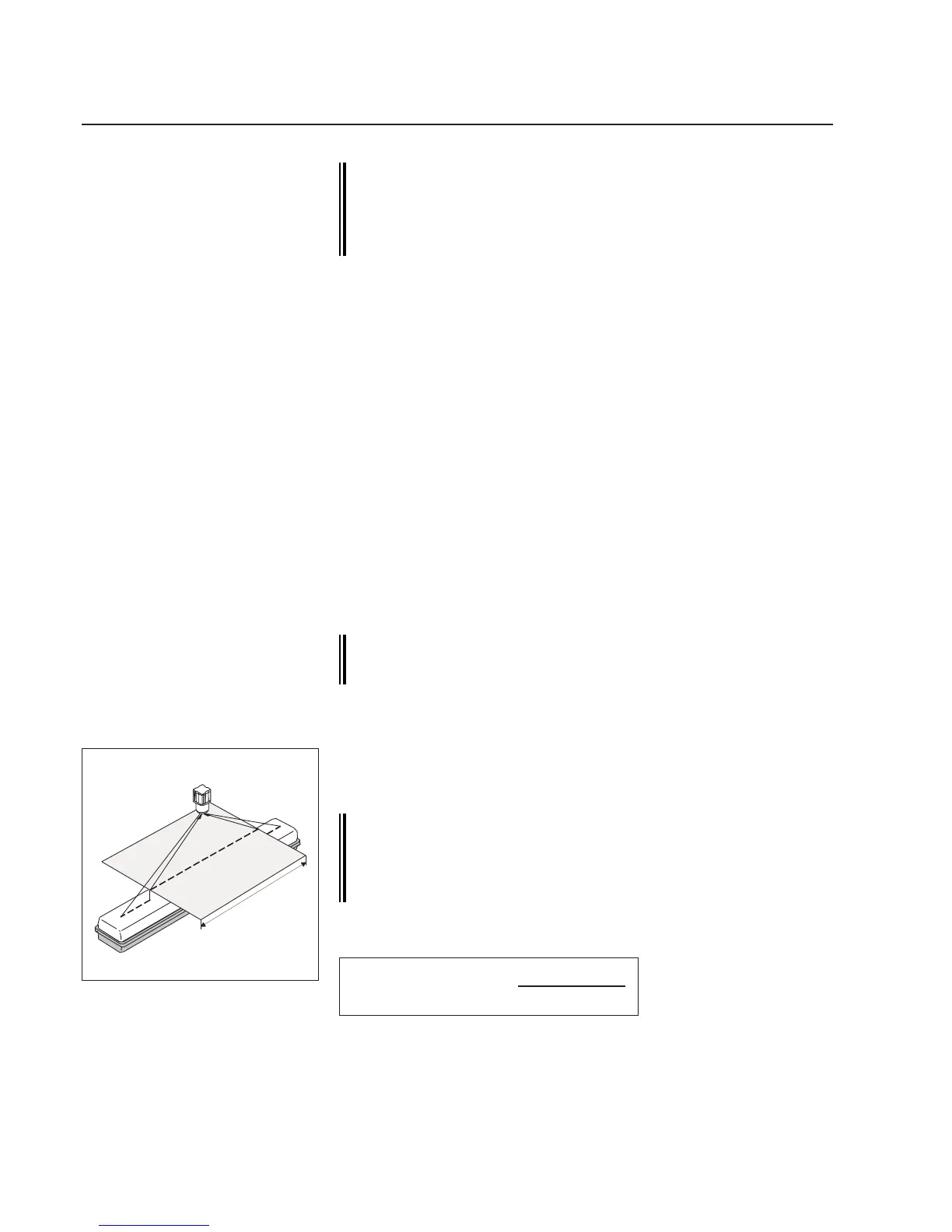
7.8.1 Standard calibration
Forcameracalibrationatemplateisrequiredthatisinsertedinthe
camerameasuringrangeinsteadoftheweb.Seeillustrationoppo-
site.
The template must lie within the measuring range set in the
rst measuring value (see camera conguration). It must
be positioned on the same plane as the web will run subse-
quently. It should cover as large an area of the measuring
range as possible, approx. 2/3 of the web width.
Thecameraresolutioncanbecalculatedfromthewidthofthetem-
plateandthedistancemeasured:
Standardcalibration
2/3webwidth
Resolutionperpixel=
templatewidth
coveredpixels
➜Positionthetemplateinthecameravisualrange.
➜Callupsetupeditor,seesetupeditorsection.