BEA--220265-EN-04 BPage9
CCDarraycameraOptoLineOL80..
Thelongerthelighttransmitter,thegreaterthegapwillbe.Themaxi-
mummountingdistancecanbecalculatedasfollows:
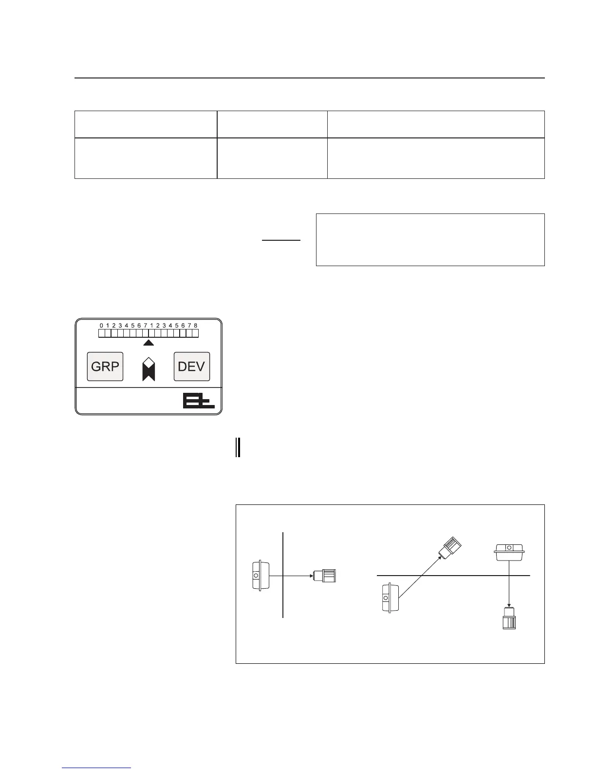
Ifthecameralooksdownonthewebfromabove,itshouldbemount-
edsothatthearrowonthecameraoperatingcontrolspointsinthe
directionofwebtravel.Ifthecameralooksuptothewebfrombelow,
thearrowshouldpointintheoppositedirectiontothatofwebtravel.
OncamerasystemsdesignedbyE+L,themodulereferencemust
alsobechecked(e.g.B2).Theblockdiagramspeciesexactly
whichcamerashouldbemountedonwhichsideoftheweb,seen
fromthedirectionofwebtravel.
TwodifferentE+Lsupportsareavailableformountingthecamera,
seeattacheddrawing.
We recommend you pin the supports once the camera has
been positioned (7.1 commissioning).
Howthelighttransmitterismounteddependsonthescanningpro-
cessimplemented.
M= Max.mountingdist.camera-lighttransmitterMinmms
a = Lighttransmitteroperationalrangeinmms
b = CCDelementlength=28,67mm
f =Lensfocallength(24,28or50mm)
Verticalwebtravel Horizontalwebtravel
5.4 Camera assembly
5.5 Light transmitter assembly
Lighttransmitterassemblywith
backlightingprinciple
Lighttransmitterlength Lighttransmitterh Maximummountingdistancecamera-lighttransmitterM
FS16.1 FS16.2 operationalrange OL8024 OL8028 OL8050
665mm 685mm 450mm 400mm 460mm 830mm
1275mm 1295mm 1050mm 900mm 1050mm 1880mm
1575mm 1595mm 1350mm 1150mm 1340mm 2400mm
M=
f(a+b)
b
1.
2. 3.
Whenusing backlightingwerecommendthethreemountingvari-
antsabovetoavoidsoiling.
ThefollowingtableliststhemaximumdistanceofstandardE+L
transmitterstothecamera.