16
At the first start up of the instrument or when it is desired to modify
a configuration parameter proceed as follows.
The instrument should be in STAND BY mode or in NORMAL
DISPLAY MODE.
Depress the SET UP/INS push-button. The display will show the
following:
This instrument is capable to performing, during TC and RTD
measurement, an open input test (the instrument injects a 100 mA
impulse signal).
When this test is desired, select YES and depress the FUNC push-
button.
The display will show:
Where :
SERIAL LINK
To enable the serial communication.
DIGITAL INP
To enable the logic inputs.
NONE
Both options are disabled.
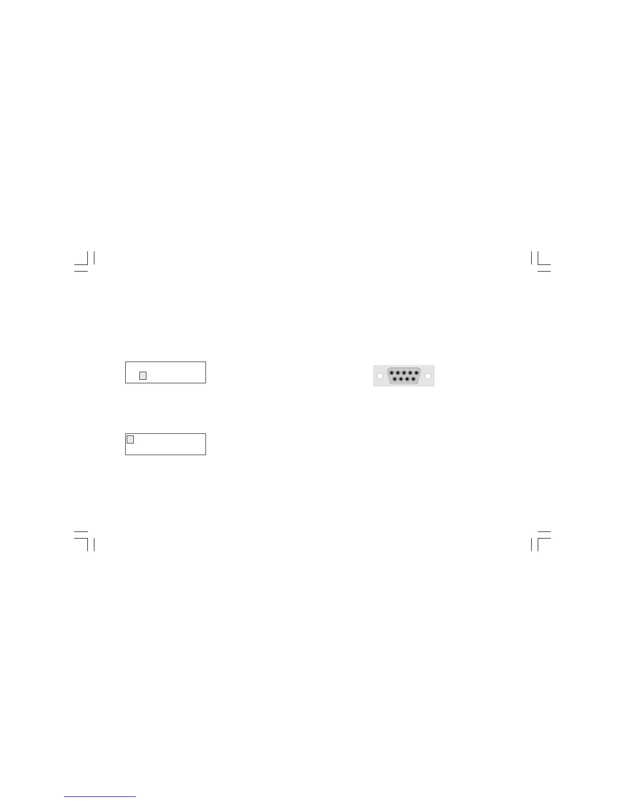
2.3.1 SERIAL LINK
RS-232 connection diagram
Pin Description
1 RESERVED
2 - RS232 receiver data (RX)
- Logic input 1 (step advance)
3 RS232 transmitter data (TX)
4 Positive voltage for logic input
5 Signal ground for RS232
6 RESERVED
7 RTS Request to send (used by the RS 232/RS485
converter).
8 Logic input 2 (RUN/WAIT)
9 RESERVED
OPEN INPUT TEST?
YES NO
SERIAL LINK
DIGITAL INP NONE
5 4 3 2 1
9 8 7 6
M20-e-2.p65 7/9/01, 2:40 PM16
 Loading...