TORCH DATA 100i-400i 196 Manual 0560956430
Stainless Steel
Flow Rates (SLPM / SCFH)
400A
H35 N₂
Preow
- / - 207 / 439
H35 Plasma / N₂ Shield
Culow
47 / 100 173 / 367
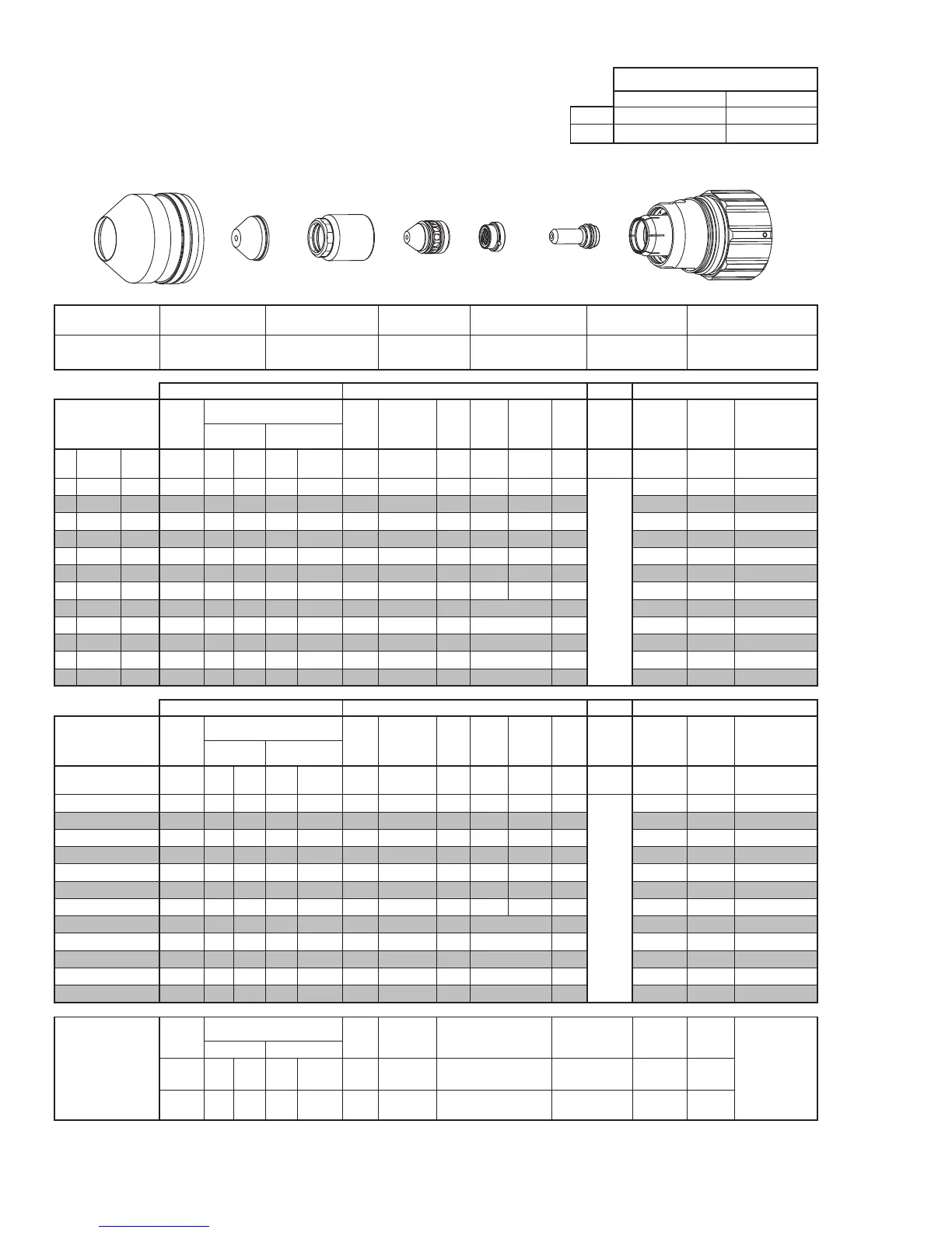
Shield Cup
Shield Cap
Shield Gas
Distributor
Tip
Gas
Distributor
Electrode
Cartridge Assembly
This Art Is For Reference Only
Art# A-10444
Shield Cup Shield Cap
Shield Gas Distributor
Tip Plasma Gas Distributor Electrode Cartridge
0559211401
≤ 1” / 0559210154
> 1” / 0559210155
0559210083 0559210132 0559210065 0559210112 0559211400
Manual Gas Control Advanced Torch Height Control (THC) Basic THC CNC Control
Material
Thickness
Pre Flow
Pressure
(N₂)
Cut Flow Rates / Pressures
Arc
Voltage
Cut Height
THC
Pierce
Delay
Pierce
Ignion
Height
Elevaon
Height
Control
Delay
Pierce
Height
without
Elevaon
Travel
Speed
CNC
Moon
Delay
Max Kerf Width
@ Rec. Speed
Plasma (H35) Shield (N₂)
ga (in) inch (psi) Ball (psi) Ball (psi) (Volts) (in) ±0.005 (sec) (in) (in) (sec) (in) (ipm) (sec) (in)
- 5/8 0.625 30 120 100 NA 110 155 0.350 0.5 0.400 0.400 0.2
Not Recommended without
Elevaon Height
70 0.4 0.230
- 3/4 0.750 30 120 100 NA 110 157 0.350 0.6 0.400 0.400 0.2 60 0.5 0.230
- 1 1.000 30 120 100 NA 110 161 0.350 1.0 0.400 0.500 0.2 45 0.8 0.236
- 1 1/4 1.250 30 120 100 NA 110 163 0.350 1.5 0.400 0.500 0.2 35 1.2 0.235
- 1 1/2 1.500 30 120 100 NA 110 165 0.350 1.8 0.400 0.500 0.2 28 1.3 0.248
- 1 3/4 1.750 30 120 100 NA 110 167 0.350 5.0 0.400 0.750 0.2 20 2.5 0.257
- 2 2.000 30 120 100 NA 110 171 0.350 10.0 0.400 0.750 0.2 17 5.5 0.268
- 2 1/4 2.250 30 120 100 NA 110 175 0.350 3.0 Edge Start 0.2 12 3.0 0.265
- 2 1/2 2.500 30 120 100 NA 110 170 0.350 3.0 Edge Start 0.2 14 3.0 0.260
- 3 3.000 30 120 100 NA 110 177 0.350 3.0 Edge Start 0.2 10 3.0 0.275
- 3 1/2 3.500 30 120 100 NA 110 195 0.350 3.0 Edge Start 0.2 5 3.0 0.280
- 4 4.000 30 120 100 NA 110 210 0.350 4.0 Edge Start 0.2 3.5 4.0 0.290
Manual Gas Control Advanced Torch Height Control (THC) Basic THC CNC Control
Material
Thickness
Pre Flow
Pressure
(N₂)
Cut Flow Rates / Pressures
Arc
Voltage
Cut Height
THC
Pierce
Delay
Pierce
Ignion
Height
Elevaon
Height
Control
Delay
Pierce
Height
without
Elevaon
Travel
Speed
CNC
Moon
Delay
Max Kerf Width
@ Rec. Speed
Plasma (H35) Shield (N₂)
(mm) (Bar) Ball (Bar) Ball (Bar) (Volts) (mm) ±0.1 (sec) (mm) (mm) (sec) (mm) (mm/ min) (sec) (mm)
15 2.1 120 6.9 NA 7.6 154 8.9 0.5 10.2 10.2 0.2
Not Recommended without
Elevaon Height
1850 0.4 5.8
20 2.1 120 6.9 NA 7.6 158 8.9 0.7 10.2 10.5 0.2 1470 0.5 5.9
25 2.1 120 6.9 NA 7.6 161 8.9 1.0 10.2 12.5 0.2 1170 0.8 6.0
30 2.1 120 6.9 NA 7.6 162 8.9 1.4 10.2 12.7 0.2 960 1.1 6.0
35 2.1 120 6.9 NA 7.6 164 8.9 1.7 10.2 12.7 0.2 800 1.3 6.1
40 2.1 120 6.9 NA 7.6 166 8.9 2.8 10.2 14.6 0.2 650 1.7 6.4
50 2.1 120 6.9 NA 7.6 170 8.9 9.4 10.2 19.1 0.2 440 5.1 6.8
60 2.1 120 6.9 NA 7.6 173 8.9 3.0 Edge Start 0.2 330 3.0 6.7
70 2.1 120 6.9 NA 7.6 174 8.9 3.0 Edge Start 0.2 300 3.0 6.8
80 2.1 120 6.9 NA 7.6 182 8.9 3.0 Edge Start 0.2 220 3.0 7.0
90 2.1 120 6.9 NA 7.6 196 8.9 3.1 Edge Start 0.2 120 3.1 7.1
100 2.1 120 6.9 NA 7.6 208 8.9 3.9 Edge Start 0.2 90 3.9 7.3
Marking
Pre Flow
Pressure
(N₂)
Marking Flow Rates / Pressures
Arc
Voltage
Marking
Height
Pierce Ignion Height
THC and CNC
Delay
Control
Delay
Travel
Speed
Marking quality
degrades as
thickness
decreases.
50A Arc Current
Plasma (N₂) Shield (N₂)
(psi) /
(Bar)
Ball
(psi) /
(Bar)
Ball
(psi) /
(Bar)
(Volts)
(in) ±0.005 /
(mm) ±0.1
(in) ±0.005 / (mm) ±0.1 (sec) (sec)
(ipm) /
(mm/ min)
15 / 1.0 80
80 /
5.5
NA 20 / 1.4 91 0.250 / 6.4 0.120 / 3.0 0 0.4
100 /
2540
BOLD TYPE indicates maximum piercing parameters. BOLD ITALIC indicates edge starts only.
Note 1: For best results when cung 4” or 100mm Stainless Steel, H35 can be used for both Plasma and Shield gas.
 Loading...