24
3.2 Primary Input Electrical Connections
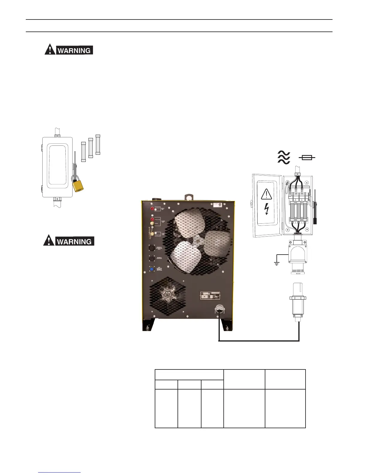
1. A line (wall) disconnect switch, with fuse or circuit breakers, should be
provided at the main power panel. See Fig. 3. The primary power leads
should be insulated copper conductors, and include three power leads
and one ground wire. The wires may be heavy rubber covered cable, or
may be run in a solid or exible conduit. Refer to Table 1 for recommended
input conductors and line fuse sizes.
It is of the utmost importance that the
chassis be connected to an approved
electrical ground to prevent accidental
shocking. Take care not to connect the
ground wire to any of the primary leads.
Precautionary measures should be taken
to provide maximum protection against
electrical shock. Be sure that all power is
o by opening the line (wall) disconnect
switch and unplug the power cord to the
unit use proper lock out safety procedures
when making primary electrical connec-
tions to the power supply.
FIG 3. Typical Installation - User
Supplied 3 Phase Fused Power
Disconnect Box with Recepticle
and Plug
Input Requirements Input & Gnd. Fuse Ratings
Conductor /Phase, Amps
Volts Phase Amps CU/AWG
220 3 121 No. 1 150
230 3 116 No. 1 150
380 3 70 No. 4 100
415 3 64 No. 6 90
460 3 58 No. 6 80
575 3 45 No. 6 70
Table 3-1. Input Conductor and Line Fuse Size
Recommendations
Sizes per National Electrical Code for 75
o
rated conductors @ 30
o
C ambient.
Not more than three conductors in raceway or cable. Local codes should be
followed if they specify sizes other than those listed above.
SECTION 3 INSTALLATION