29
3.4 Torch Connections
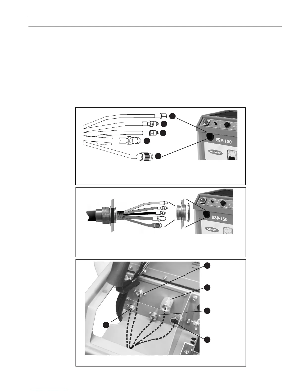
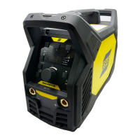
1. Open top front cover to gain access to the torch connections.(Fig. 10)
2. Thread the ve service lines (gas, power, and switch lead) of the PT-26 torch through bushing at upper left corner of the
front panel and connect them to the matching ttings on output terminal. Hose connections should be wrench-tight.
Make sure plug of the switch lead is rmly locked in place. Then close and reinstall the hinged cover.
a. If a PT-26 In-line Torch is being used in a mechanized installation where only an arc start signal is required, connect
the optional Remote Hand Switch, ESAB part number 2075600, to the Torch Switch Receptacle on the hook-up panel
in the front of the ESP-150 console. Fig. 11.
b. If a PT-26 In-line Torch is being used in a mechanized installation with a CNC device, see Fig. 9 for Remote Control
Receptacle I/O signal pin conguration and Fig. 8 for Control Mode Selection instructions.
Water OUT (-)
(Torch)
Water IN (+)
(Pilot Arc)
Shield
Gas
4
2
+
+
-
-
Fig. 12 - Interconnection Diagram - Front of ESP-150
Plasma/Start
Gas
Torch Switch
Receptacle
3
5
Fig. 11 - For Mechanized applications using a shielded in-line torch, remove
the rubber grommet slide body through sheet metal front of ESP-150 and tighten
with locknut.
Fig. 10 - For manual torch applications, pass the service connections through the
rubber grommet in the front of ESP-150 and make connections as shown.
1
2
3
4
5
1
SECTION 3 INSTALLATION