51
15. The thermal cut-out trips frequently.
Make sure that you are not exceeding therated data for the power source (i.e. that theunit is not being over-
loaded).
16. Poor welding performance.
Check that the welding current supply andreturn cables are correctly connected.Check that the correct current
value is set.Check that the correct electrode is beingused.Check the mains power supply fuses.
B. SEQUENCE OF OPERATION
1. Close primary disconnect switch.
a. Power supplied to unit.
2. Place Power Switch (ROS) to “Ready” position.
a. Fan motor (FM) and Pump motor on.
b. Low Gas LED on.
c. Control circuit energizes.
3. Place Gas Mode Switch (OSS) to “CUT” position.
a. Gas solenoid valves (CGSV) energize. Gases ow to permit setting of pressures and to purge system.
4. Place OSS to “Operate” position.
a. Gas valves (PGSV and CGSV) deenergize to stop gas ows.
5. Depress torch switch.
a. SHSV and SGSV (shield and start) gas solenoid valves open to allow gases to ow to torch.
b. Pilot Arc Contactor (PAC) closes.
c. High Frequency (HF) energizes.
d. Pressure Switches (PGPS & CGPS) close (provided gas pressures are set above 19 psig on PGPS and 22 psig
on CGPS).
e. Two seconds later, Main Contactor (MC) closes to establish pilot arc.
f. Pilot arc will transfer to cutting arc within 6 seconds as long as torch is close enough (1/8” —1/4”) to
work.
g. HF and PAC deenergizes immediately when cutting arc is established, or after 6 seconds of continuous
pilot arc. If cutting arc is not established after six seconds, MC will open but the HF will remain energized.
MC and pilot arc will then cycle on and o every 3 seconds, MC will open but the HF will remain energized.
MC and pilot arc will then cycle on and o every 3 seconds until torch switch is released.
PREFLOW & HF****
2 sec.
HF and MC*
6 sec.
CUTTING ARC** POSTFLOW***
10 sec.
PAC opens
HF deenergizes
PGSV/CGSV closes
PGPS/CGPS opens
FS opens
Release Torch
Switch
MC opens
Push
Torch Switch
PGSV/CGSV opens
PAC closes
HF energizes
PGPS/CGPS closes
FS closes
MC closes
* HF and MC remain on for approximately 6 sec. unless a main arc is established. If a main arc is not established the MC will open after 6
sec. but HF stays on. If torch switch is not released MC will cycle on and o every 3 sec. until torch switch is released.
** Cutting arc actually starts during the HF phase when the arc transfers to the workpiece anywhere between 2 and 6 seconds; Pilot arc
circuit and high-freq. generator will then shut o immediately.
*** A new cycle may be started anytime in the Postow phase, which will cancel remaining postow time and start again with the normal
preow time.
**** On units made for Advance Systems cutting machines, HF activates when MC closes at end of 2 second preow.
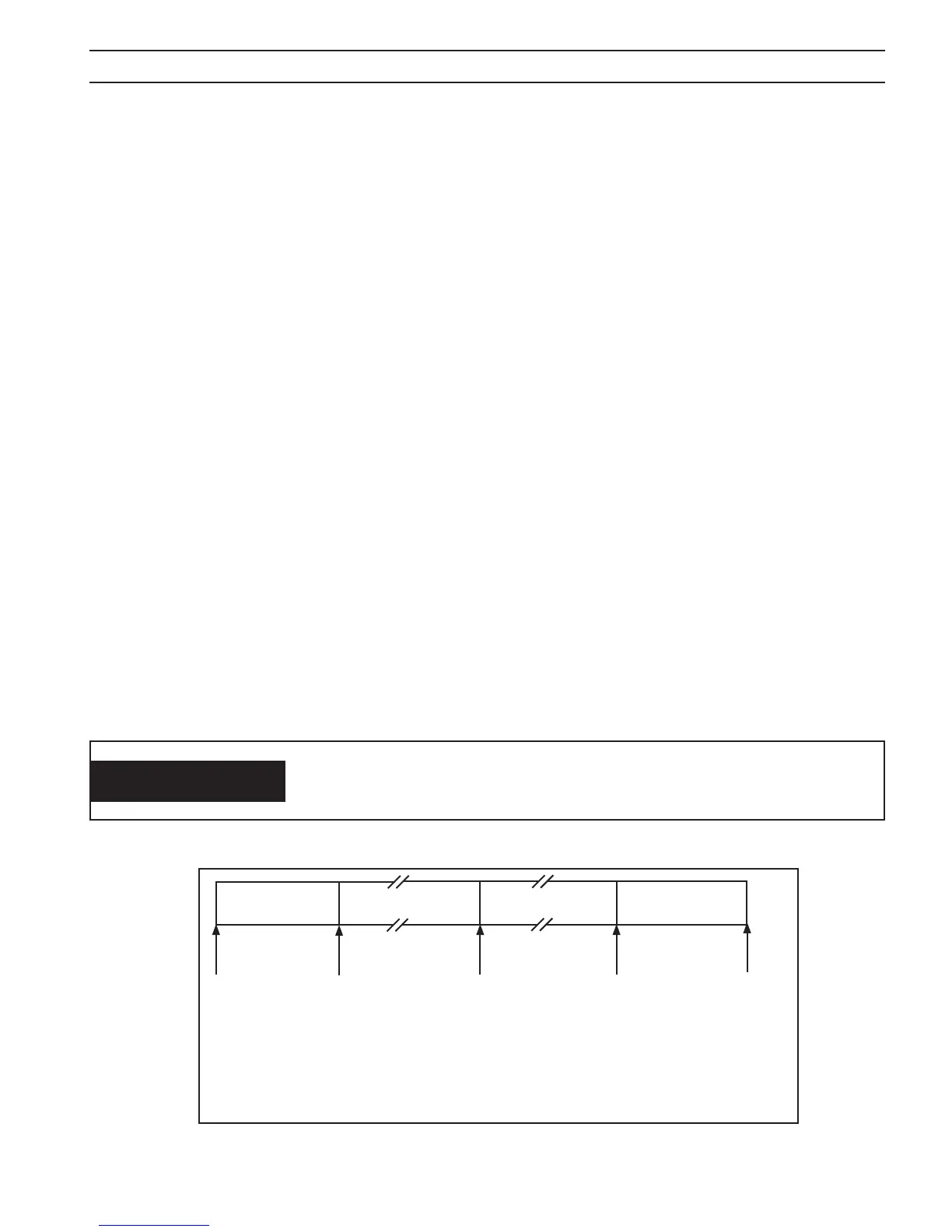
Fig. 22 - Torch Operation Sequence Diagram
SECTION 5 MAINTENANCE
WARNING
DANGEROUS HIGH VOLTAGE OVER 300 VOLTS EXISTS AT THE TORCH
FRONT END WHENEVER MC IS CLOSED; THEREFORE, RELEASE TORCH
SWITCH WHEN CUTTING IS NOT ESTABLISHED AND REPEAT STEP 5.