P28/54 T-SM47j
1
3
7
26
5
8
10
10
6
4
25
21
23
15
12
2
20
22
19
18
24
14
13
16
17
11
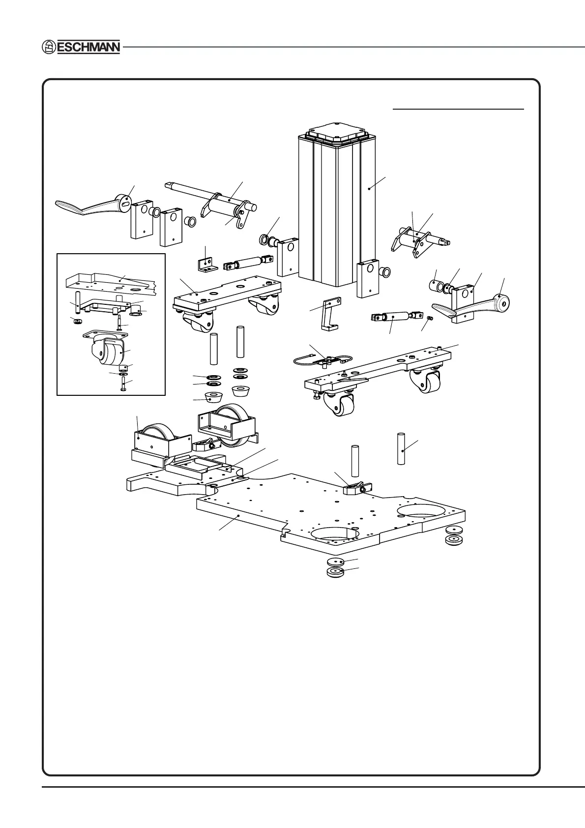
1 Base plate
2 Column assembly
3 Brake pad
4 Front wheel assembly
5 Castor pillar
6 Catch assembly
7 Standby battery tray
8 Front castor plate spacer
9 Brake pad spacer
10 Disc spring
11 Rear castor plate assembly
12 Front castor plate assembly
13 Static discharge resistor assy
14 Rear damper anchor bracket
15 Front damper bracket
16 Damper
17 Damper clevis pin*
18 Pedal anchor block
19 Headed bush
20 Rear pedal spindle assembly
21 Front pedal spindle assembly
22 Rear pedal shaft spacer
23 Front pedal shaft thrust ring
24 Rear pedal
25 Front pedal
26 Front castor plate shim
27 Castor plate
28 M10 x 50mm Screw
27
28
29
30
31
32
33
34
35
36
TYPICAL CASTOR ASSY.
29 M10 nut
30 Castor insulation pad
31 Castor pillar bush
32
Static discharge connector
33 Castor
34 Isolating bush
35 Special washer
36 Hex. hd. set bolt
37 Lifting roller assembly
38 Lifting roller spindle
37
38
* or use clip supplied as part of Damper
9
Fig. 6.2c Table base general arrangement (internal pedal catch and
increased height, Serial Numbers prefixed T2AC or later)
Torque settings
M10 x 40mm screws securing
item 1 to item 2 = 40Nm.
Castor screws = 4Nm
Note: During maintenance of the front pedal or castor
plate assembly it may be necessary to use shims
(item 26). If pedal can be pressed past the locking
point too easily then add a shim. If too many shims
are added the pedal may be difficult to release.