T-SM47j P39/54
T20-a
OPERATION TABLE
vii Continue to reassemble the table by reversing the
above (use threadlock part number 670650 on screw
threads and note any applicable torque values
shown on Fig. 6.5 and 6.6). Ensure all electrical
connections are remade and all looms are secured
as found and carry out a full function test.
6.5.2.5 Side rails
To replace a long or short trunk side rail proceed as follows,
traversing the table (fully cranially) as required to gain
access to the fixing screws:
i Remove the screws securing the side rail from
beneath the table top on the inside edge of the side
arms (items 15 and 17 of Fig. 6.6 and items 10 and
16 of Fig. 6.5). Note that on the long trunk section
there is a central short screw that can be released
through the hole on the inside of the side arm.
ii Secure the new side rail to the section (use
threadlock part number 670650 on screw threads
and note torque value of 21Nm).
6.5.2.6 Top covers
To remove or replace a long or short trunk top cover
proceed as follows, traversing the table as required to gain
access to the fixing screws:
i Remove the side rails as detailed in section 6.5.2.5
and then the small screws securing the lower edge
of the cover to the side arms.
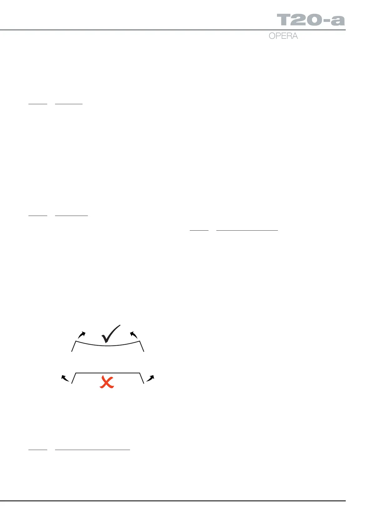
ii Remove the screw cover on the mattress retaining
screws and then remove the mattress retainers.
Carefully release the lower edge of the cover on
each side and flex the cover from the middle to
release it, not by bending out the sides, see diagram
below. Take care not to damage it if it is to be reused
and not replaced.
iii To replace the cover reverse the above using
threadlock part number 670650 on all screw threads
(except the small M3 Torx screws retaining the lower
edge of the cover, note torque setting of 0.5Nm for
these) and note any other applicable torque values
shown in Fig. 6.5 and 6.6.
6.5.2.7 Push button components
The push button assembly (locking or non-locking) does not
require any special adjustment after assembly. Should any
part require replacement or cleaning follow the method below
to take the assembly apart and reassemble it, replacing parts
as required during the procedure. On the short trunk it will
be necessary to remove the ‘P’ clip on the break gearbox
loom and the bottom cover (item 3 and 11 of Fig. 6.6).
i Remove the ‘R’ clip in the end of the push button
from below the table top. This will release all the
push button components (locking or non-locking).
ii Slide out the push button with its return spring and for
the locking push button push the plunger (i.e. item 4 of
Fig. 6.5) out the back of the attachment block which
will eject the ball bearing and compression spring.
iii Clean or replace components as required, clean out
any debris from recess and reassemble without
lubrication. Ensure that on assembly the slot in the
top of the push button blade is correctly positioned
over the roll pin in the attachment block.
iv Reassemble the table (use threadlock part number
670650 on screw threads and note any applicable
torque values shown in Fig. 6.5 and 6.6 ) replacing
the ‘P’ clip and the bottom cover if removed and
check button function by attaching and removing a
suitable table section several times.
6.5.2.8 Traverse rod bearing
To replace the traverse rod bearings item 3 of Fig. 6.7
(always replace as a set of four) proceed as follows:
i Remove the long trunk section cover as 6.5.2.6.
ii Remove the short trunk bottom covers (items 3 and
11 of Fig. 6.6) and release connections from the
break potentiometer loom and connections from the
break motor where they join the break motor loom .
iii Remove the four M8 countersunk screws securing
the short trunk in place (two either side) and remove
the short trunk by sliding the gearbox arms out of
the long trunk.
iv Remove the set screws securing the end of the lead
screws (items 13 of Fig. 6.5) and remove the black
top (items 17 of Fig. 6.5) from the long trunk section.
v Remove the black top location dowels from the break
attachment blocks (items 11 and 14 of Fig. 6.5) and
all the button head screws.
vi Whilst supporting each side arm in turn withdraw
the break attachment blocks.
vii Slide out the traverse rods and knock out the
traverse rod bearings.
viii Carefully replace the new set of bearings and
reassemble the table by reversing the above (use
threadlock part number 670650 on screw threads,
see note on Fig.6.6 and note any applicable torque
values shown in Fig. 6.5, 6.6 and 6.7 (e.g. lead screw
set screw 20Nm black top screws 6Nm). Ensure all
electrical connections have been made.
ix Test all table functions.