P42/54 T-SM47j
6.6.2 Three actuator PCA
To replace a three actuator PCA (item 18 of Fig. 6.7)
proceed as follows:
i Place table into the ‘Service position’ as detailed in
section 1.9 (noting safety warnings) and then
remove the bottom crossbeam cover (item 17 of Fig.
6.7).
ii Remove all connections to the three actuator PCA
and remove it from within the crossbeam.
iii Replace the new three actuator PCA with the old
insulation sheet, reconnect all the connections and
then check Appendix 2 and proceed as detailed in
the ‘Application software manual’.
iv Reassemble the table and carry out a full table
function test.
6.6.3 Four actuator PCA
To replace a four actuator PCA (item 23 of Fig. 6.3) proceed
as follows:
i Gain access to the upper column as detailed in
section 6.2.3.
ii Remove all connections to the four actuator PCA and
remove it from the column (remove the four M4
screws and take care not to loose the four small
spacers).
iii Replace the new four actuator PCA with the insulation
sheet and spacers as found, reconnect all the loom
connections and then check Appendix 2 and proceed
as detailed in the ‘Application software manual’.
iv Reassemble the table and carry out a full table
function test.
6.6.4 Infrared receiver PCA
To replace an infrared receiver PCA proceed as follows:
i Remove the appropriate base cover as detailed in
section 6.2.2 (take care of loom to PCA).
ii Remove the infrared receiver PCA from inside the
cover. These are held in place with two plastic rivets,
simply pull out the rivet to release the PCA, the
mount will remain on the cover.
iii Replace the new PCA and secure in place with the
two rivets, reassemble and carry out a full table
function test.
1
2
3
4
5
6
7
8
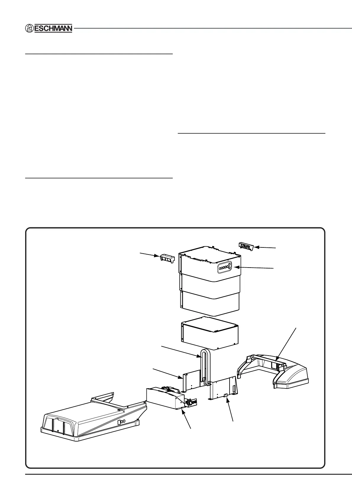
1 Switch panel loom
2 Accessory panel loom
3 Column energy chain loom
4 Cover support bracket r/h
5 Cover support bracket l/h
6 Power supply assembly (see above)
7 Mains indicator panel loom
8 Standby panel loom
Fig. 6.8 Table base main electrical components