T-SM47j P33/54
T20-a
OPERATION TABLE
6.5 TABLE SECTIONS
This section is split into two parts as follows:
6.5.1 Head and leg section (see Fig. 6.4).
6.5.2 Trunk sections, long and short (see Figs. 6.5 to 6.7).
6.5.1 Head and leg section
The following parts may need replacement in the event of
wear or damage (see notes below in each section) and
the procedures for these are detailed below:
6.5.1.1 Guide pins
6.5.1.2 Gas springs
6.5.1.3 Cover
6.5.1.4 Gas spring release head / pivot pin
6.5.1.5 Gas spring release handle
6.5.1.6 X-ray translucent top
See Fig. 6.4 for the general arrangement of the head and
leg section assembly, the figure shows the leg section, but
note that the head section is similar (no cross bar or middle
side bar screws).
6.5.1.1 Guide pins
To replace a guide pin if worn or damaged remove the
retaining screw and refit a new pin. Apply threadlock to the
screw (part number 670650) and lubricate the pin sparingly
with grease (part number 110477). Tighten securing screw
to a torque setting of 8Nm. Check section fits table correctly.
6.5.1.2 Gas springs
WARNING
Gas springs are filled with high-pressure gas.
DO NOT attempt to open them, see section
6.5.1.2 (vii) before disposal.
CAUTION
Gas springs do not require
additional lubrication.
To replace a gas spring if it shows sign of oil leakage or
has become spongy (pressure applied on one side of the
section produces noticeably more movement than the
other) proceed as follows:
i Remove section from table and rest it on a suitable
work surface upside down.
ii Remove the shoulder screw in the mounting block
at the cylinder end.
iii Release locking nut at the end of the piston and
unscrew gas spring piston from release head casting.
iv Wind nut on the new gas spring well down thread,
lubricate actuating nipple with grease (part number
110477). Screw gas spring into the release head
casting until play has been removed between the
release handle actuator and the gas spring release
button, then back off approximately half a turn. Apply
threadlock (part number 670650) and tighten the
piston-locking nut onto the release head casting.
v Apply grease (part number 110477) to the shank
and threadlock (part number 670650) to the thread
of the shoulder screw and replace it into the
mounting block, tighten to a torque setting of 10Nm.
vi Actuate the release lever to align the guide pins and
replace section into a table trunk section. Check that
the section works correctly and that both gas springs
are working together, adjust if required as ‘iv’ above
and remove any excess threadlock.
vii. Before disposing of the gas spring it is suggested
that the high pressure gas is released from within
the cylinder to avoid the possibility of injury (or return
it to Eschmann Equipment). To release the gas
(nitrogen and a small amount of hydraulic oil) locate
the gas spring positively onto the bed of a drilling
machine taking care not to puncture the cylinder.
Do not centre punch to provide a drill guide as this
may rupture the cylinder and wear suitable eye and
hand protection. Use a 2-3mm diameter drill at slow
speed and drill a hole 25-30mm from the mounting
end of the cylinder to a depth of half the cylinder
diameter to vent the gas. Clean up any oil spillage.
6.5.1.3 Top cover
To replace a top cover if damaged proceed as follows:
i Remove section from table and rest it on a suitable
work surface upside down.
ii Remove the four M8 screws (six on the leg section)
that secure the sidebars.
iii Turn section over and remove the mattress retainers.
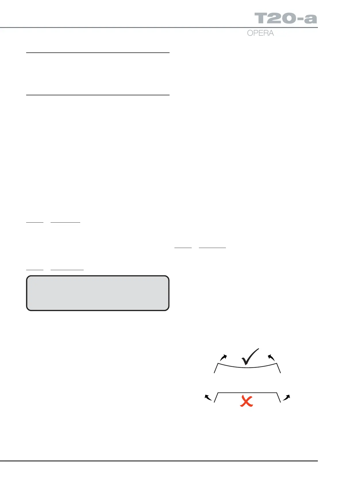
iv Carefully release the lower edge of the cover on
each side and flex the cover from the middle, do not
bend out the sides, see diagram. Replace cover with
the new one and replace the mattress retainers
using threadlock (part number 670650) on the screw
threads.
v Replace the sidebars and secure using threadlock
(part number 670650) on the screw threads and
tighten to a torque setting of 15Nm. Finally check
section function.