Class II Biological Safety Cabinets
Cause Corrective Action
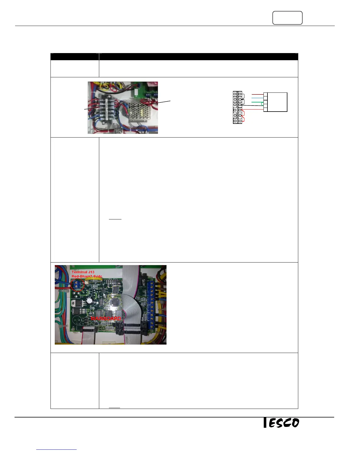
• If input voltage exists but there is no output voltage, please replace the SMPS.
• If input and output voltage is correct, please Proceed to the next step.
Connection
problem to main
board or from
main board to
display
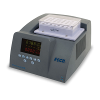
• Measure the incoming voltage on the main board at terminal J 13 (Note polarity, blue
cable closest to edge is negative -). See Figure 1-5.
• Voltage should be between 6.75 – 8.25VDC, if 7.5 VDC SMPS (item code 1080328) is
used.
• Voltage should be between 10.8 – 13.2VDC, if 12 VDC SMPS (item code 1080945) is
used.
• If voltage is out of range or no voltage, ensure adequate connection between SMPS
and main board.
• Ensure adequate connection between flat ribbon cable from main board to
LCD/keypad membrane.
NOTE: There are two ribbon cables from the main board and the display and key pad. The
larger flat cable is for the Display. The smaller flat cable is for the LEDs/keypad membrane.
• If the LCD Display is on, but not the LEDs in keypad membrane, check connection on
the smaller Flat Ribbon cable.
• If the incoming voltage at J13 is of right voltage and flat ribbon cable are connected
adequately but the LEDs on the keypad membrane and LCD display are still not
Defective main
board
• The main board is defective if the main board incoming supply is between 10.8 –
13.2VDC if 12 VDC SMPS is installed and:
o All LED’s on the control panel are off.
o The LCD is blank.
o No buzzer sound.
• If these conditions exist replace the main board, otherwise Proceed to the next step
Note: when replacing main board, reconnect all wires correctly, any wrong wiring may result in
SMPS output
Red-
Black/blue is
12 VDC
Blue-G/Y is 115 VAC or
230 VAC
Figure 1-4
Brown
Negatif
Positive
SMPS
Terminal block