EasyManua.ls Logo

ESDEC FLATFIX WAVE - User Manual

ESDEC FLATFIX WAVE
20 pages
Print Icon
To Next Page IconTo Next Page
Loading...
www.esdec.com
REV01
MANUAL
FLATFIX WAVE
Question and Answer IconNeed help?

Do you have a question about the ESDEC FLATFIX WAVE and is the answer not in the manual?

Summary

General Installation Conditions

General

Manufacturer reserves right to change document without notice.

Stability and condition of the roof

Roof must be structurally sound to support system load, wind, and snow.

Safety warnings

Emphasizes qualified personnel, fall protection, and safe working practices.

Range of application of FlatFix Wave

Defines system suitability for wind zones, terrain, building heights, and roof types.

Edge area

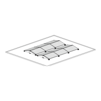
Specifies critical distance from panels to roof edge due to wind turbulence.

Ballast

Recommends consulting supplier for ballast on roofs over 12m high.

Standards, regulations and rules

Lists applicable building, electrical, and safety standards for installation.

Removal and disassembly

Instructions for product disposal and recyclability.

Warranty

Details warranty terms available on the Esdec website.

Liability

Manufacturer disclaims liability for non-compliance or negligence.

Bill of Materials

UNITS

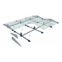
Lists different types of FlatFix Wave dual units.

STABILIZERS

Lists various stabilizer components for the system.

WIND DEFLECTORS

Details wind deflector components and their parts.

ACCESSORIES

Lists available accessories for the FlatFix Wave system.

TOOLS & EQUIPMENT

Illustrates tools and equipment potentially needed for installation.

Preparations for Assembly

1 PREPARING THE ROOF AND ALIGNING (THE FIELDS)

Ensures roof condition and proper alignment of installation fields.

2 MEASURING AND MARKING (OF FIELD)

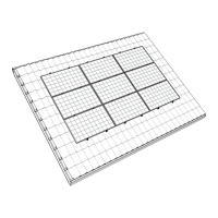
Covers space calculation, field contour marking, and panel placement.

Place Dual Start Unit

1 PLACE THE DUAL START UNIT DIRECTLY ON THE RIGHT PLACE ON THE ROOF

Places the dual start unit correctly on the roof surface.

3 PLACE THE HIGH BASE (2 x) IN STANDING POSITION SO THAT IT CLICKS

Positions high base elements correctly for engagement.

Positioning the Dual Start Units

1 POSITION THE 2 nd DUAL START UNIT

Positions the second dual start unit at the edge of the field.

2 POSITIONING OF THE OTHER DUAL START UNITS

Aligns and positions subsequent dual start units.

Place Dual Units

1 PREPARE COUPLING

Prepares the coupling mechanism for connecting units.

2 COUPLE DUAL UNITS TO THE DUAL START UNITS

Details coupling dual units to the dual start units.

4 PLACE THE HIGH BASE (2 x) IN STANDING POSITION SO THAT IT CLICKS

Correctly places high base elements for clicking.

Assembly of Stabilizers and Cable Brackets

1 POSITIONING STABILIZERS IN CONNECTION

Positions stabilizers relative to high base elements.

2 ASSEMBLE STABILIZERS ON HIGH BASE

Assembles stabilizers onto the high base elements.

3 ASSEMBLE CABLE BRACKETS ON STABILIZERS

Attaches cable brackets to the stabilizers.

Placing the Ballast

1 PLACING THE BALLAST (GENERAL)

General guidelines for ballast placement using calculator.

2 PLACE STANDARD BALLAST (3 x4 kg.)

Places standard ballast weights in units on the high base.

3 PLACE OPTIONAL BALLAST (5 x4 kg.)

Steps for placing optional ballast weights and brackets.

Assembly of Solar Panels and Cables

1 POSITION AND CLAMP THE SOLAR PANEL ON THE HIGH BASE ELEMENTS

Positions and clamps the first solar panel onto high base elements.

2 CLAMP THE SOLAR PANEL ON THE FRONT SIDE

Secures the solar panel on the front side with panel locks.

3 PLACING CABLES OR MC4 CONNECTOR

Places and connects solar panel cables and MC4 connectors.

Assemble Wind Deflector A to the Field

1 ASSEMBLE THE ROOF SUPPORTS UNDER WIND DEFLECTOR A

Assembles roof supports under wind deflector A.

2 ASSEMBLE 2 CONNECTOR PINS TO WIND DEFLECTOR A

Attaches connector pins to wind deflector A.

3 ASSEMBLE WIND DEFLECTOR A ON THE UNIT WITH CONNECTOR PINS

Mounts wind deflector A onto the unit using pins.

4 SLIDE WIND DEFLECTOR A AGAINST THE PANEL FRAME AND BEND THE FLANGE UNDER THE FRAME

Secures wind deflector A to the frame by sliding and bending.

Assemble Wind Deflector B on the Field

1 ASSEMBLE THE ROOF SUPPORT UNDER WIND DEFLECTOR B

Attaches roof supports to wind deflector B.

2 CONNECT WIND DEFLECTOR B TO WIND DEFLECTOR A

Connects wind deflector B to wind deflector A.

3 ASSEMBLE WIND DEFLECTOR B TO THE FIELD

Mounts wind deflector B onto the panel frame.

4 ASSEMBLE THE OTHER WIND DEFLECTORS A AND B ON THE REST OF THE FIELD

Repeats assembly for remaining wind deflectors.

5 THE PANEL FIELD IS NOW READY!

Confirms completion of the panel field assembly.

Annex A - Additional Roof Support

1 ASSEMBLE THE ADDITIONAL ROOF SUPPORT TO THE UNIT

Detailed steps for attaching an additional roof support to the unit.

Annex B - Manual for the Measuring Bar

1 SETTING THE MEASURING BAR

Instructions for setting up and using the measuring bar.

Annex C - Cable Management

1 TABLE

Details cable bracket requirements based on spacing and row types.

Annex D - Grounding, Bonding and Lightning Protection

1 SELECTION DIAGRAM

Flowchart for determining grounding, bonding, and lightning protection.

2 METHOD OF GROUNDING;BONDING

Explains integrated bonding and grounding methods.

3 LPS: LIGHTNING PROTECTION

Annex E - Disassembling the Panels

1 DISASSEMBLE THE PANELS

Step-by-step instructions for panel disassembly.

Overview

The Esdec FlatFix Wave is an innovative mounting system designed for the installation of solar panels on flat roofs. This manual provides comprehensive instructions for the assembly, use, and maintenance of the system, ensuring a safe and efficient installation process.

Function Description

The FlatFix Wave system serves as a robust and reliable substructure for securing solar panels on various flat roof types. Its primary function is to elevate and angle solar panels to optimize energy capture, while also providing stability against environmental factors such as wind and snow loads. The system is designed to be modular, allowing for flexible configurations to suit different roof dimensions and panel layouts. It integrates features for cable management, grounding, and lightning protection, ensuring a complete and compliant solar installation. The system's components work in conjunction to create a secure and durable platform for solar arrays, facilitating the efficient generation of renewable energy.

Usage Features

The FlatFix Wave system is engineered for ease of installation and adaptability. It is suitable for all wind zones, terrain categories, and building heights, provided the maximum wind pressure does not exceed the panel specification. The system can be installed on various roof materials including concrete, bitumen, EPDM, PVC, and TPO. For other roof coverings or roof slopes greater than 5°, consultation with the supplier is recommended. The maximum field size for installation is 40 x 40 meters.

Key usage features include:

  • Modular Design: The system consists of dual start units, dual units, stabilizers, and wind deflectors, which can be assembled in a step-by-step manner. This modularity allows for scalable installations, from small arrays to large panel fields.
  • Click System Assembly: Many components, such as the top of the dual start unit and the stabilizers, are designed with a "click" mechanism, simplifying assembly and reducing installation time. This intuitive design minimizes the need for specialized tools and complex fastening procedures.
  • Measuring Bar for Alignment: An optional measuring bar (Annex B) is available to ensure accurate positioning and alignment of the dual units, maintaining the recommended distance between panels and rows. This helps achieve a uniform and aesthetically pleasing installation.
  • Integrated Ballast System: The system incorporates a ballast feature to provide stability against wind uplift. Ballast stones (3x4 kg or 5x4 kg) are placed in designated ballast tracks and brackets on the high base elements. The installation drawing, derived from the FlatFix Wave calculator, guides the placement of ballast to meet specific load requirements. For roofs higher than 12 meters, consulting the supplier for ballast determination is advised.
  • Wind Deflectors: Wind deflectors (Type A and B) are integral to the system, designed to reduce wind loads on the solar panels and the overall structure. They are assembled to the field using connector pins and roof supports, and their flanges are bent under the panel frame for a secure fit.
  • Cable Management: The system includes provisions for cable management (Annex C), such as cable brackets and wire trays. Cables and MC4 connectors can be neatly routed and secured within the stabilizers and on cable supports, preventing damage and ensuring a tidy installation. Large and small wire trays can be assembled on the start units and high base elements, respectively, to organize wiring effectively.
  • Grounding, Bonding, and Lightning Protection: The FlatFix Wave system features integrated part bonding, eliminating the need for additional bonding between metal parts. The design ensures electrical contact between the high base elements, panel frames, and unit profiles upon tightening. Annex D provides detailed guidelines for grounding, bonding, and lightning protection, emphasizing compliance with NEN-EN-IEC 62305 and NEN1010 standards. It outlines procedures for risk analysis, LPS installation, overvoltage protection, and bonding to LPS, recommending consultation with a lightning protection specialist.
  • Safety Features: The manual highlights crucial safety warnings, including the requirement for qualified technical personnel (at least two skilled persons), the use of fall protection, appropriate footwear, and protective clothing. It also cautions against trapping hands/fingers in hinged parts during assembly.

Maintenance Features

While the manual primarily focuses on installation, it implicitly suggests aspects related to maintenance through its design and recommendations:

  • Durability: The use of high-quality, durable materials in the FlatFix Wave system contributes to its longevity and reduces the need for frequent maintenance.
  • Disassembly Instructions: Annex E provides clear instructions for disassembling the panels, which is essential for maintenance, repair, or replacement of individual panels or system components. The unlocking tool and specific steps ensure that panels can be removed safely and efficiently without damaging the system.
  • Compliance with Standards: Adherence to NEN standards (e.g., NEN 7250, NEN-EN 1990, NEN-EN 1991, NEN 1010, NEN-EN-IEC 62305) during installation ensures the system's structural integrity and electrical safety, minimizing potential issues that would require maintenance.
  • Roof Condition: The manual stresses the importance of a clean, dry, flat, and algae-free roof before installation, and the need to ensure the roof's stability. Maintaining these conditions is crucial for the long-term performance and stability of the solar array, reducing the likelihood of structural problems that might necessitate repairs.
  • Warranty: The system comes with a warranty according to Esdec BV's terms, which can be found on their website. This implies that the product is designed for reliability, and any issues covered by the warranty would be addressed by the manufacturer, reducing the burden of unexpected maintenance costs for the user.
  • Recyclability: At the end of its service life, all materials of the FlatFix Wave system are recyclable, promoting environmental sustainability and simplifying disposal procedures. The plastic roof supports and wind deflectors are attached using a click system, which likely aids in their separation for recycling.

ESDEC FLATFIX WAVE Specifications

General IconGeneral
Product CategoryRacks & Stands
Product NameESDEC FLATFIX WAVE
Mounting TypeBallasted
TypeFlat Roof Mounting System
Corrosion ResistanceHigh
ApplicationFlat Roof
MaterialAluminum
CompatibilityMost Solar Panels
Mounting Angle10°
Weight CapacityDependent on ballast, site-specific calculations required

Related product manuals