11
Fig. 21 Fig. 22
A
B
B
B
Te s ঞ ng
• Ohmmeter should read zero ohms when touching
water and ~1.2 when not touching water
• If reading is more than 10% higher, probe needs
replaced
Probe Wiring
• Part #236PECEM6
• To check if wiring is bad, test con nuity of wiring
from probe end to circuit board
b. Slide down into drain pan cup area
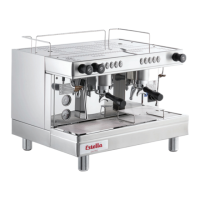
4. Remove phillips screw from group solenoid
valve wire plug (Fig. 21)
5. Pull wiring plug
6. Remove brass hex nut and copper tube
(Fig. 22 A)
7. Remove hex nut from bo om side of
valve body
8. Coil body can now be removed from valve
and tested, if needed
9. Remove 4 socket head cap screws with
3mm hex key (Fig. 22 B)
10. Note orienta on of brass moun ng fl ange
for reassembly
NOTE: Water port holes must be aligned
with holes during installa on
11. Reassemble by reversing steps
Fig. 23
Fig. 24
B
A
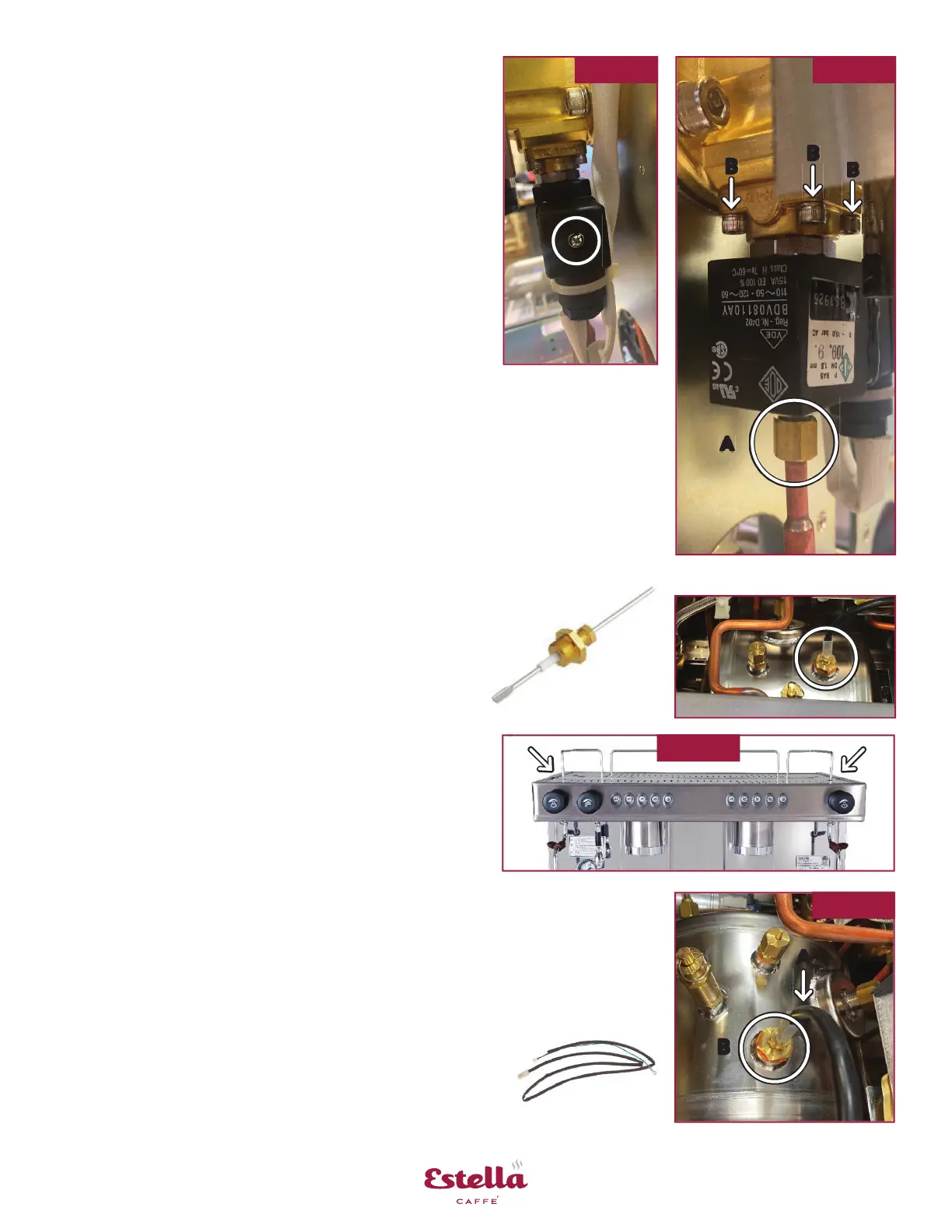
1. Follow pre-maintenance steps on page 10
2. Remove 2 screws from top rear cover (Fig. 23)
3. Carefully pull wire from water level probe (Fig. 24 A)
4. Remove probe from boiler tank (Fig. 24 B) with
19mm socket wrench, do not lose copper washer
5. Reassemble by reversing steps
6. Ensure there is no air leakage a er startup
Boiler Water Level Probe
Time Estimate: Approximately 10 min.
Part: #236PECEM17
 Loading...