10
will transmit its address continuously and thus enables the ECoS-
Detector to receive it and to transmit it to the command station. In
order to enable the RailCom® feedback configure the correspon-
ding output as described in chapter 6.4 to current sensor mode
and make sure that all ESU decoders have the latest firmware.
If the feedback input is configured as common contact the Rail-
Com® feedback cannot work.
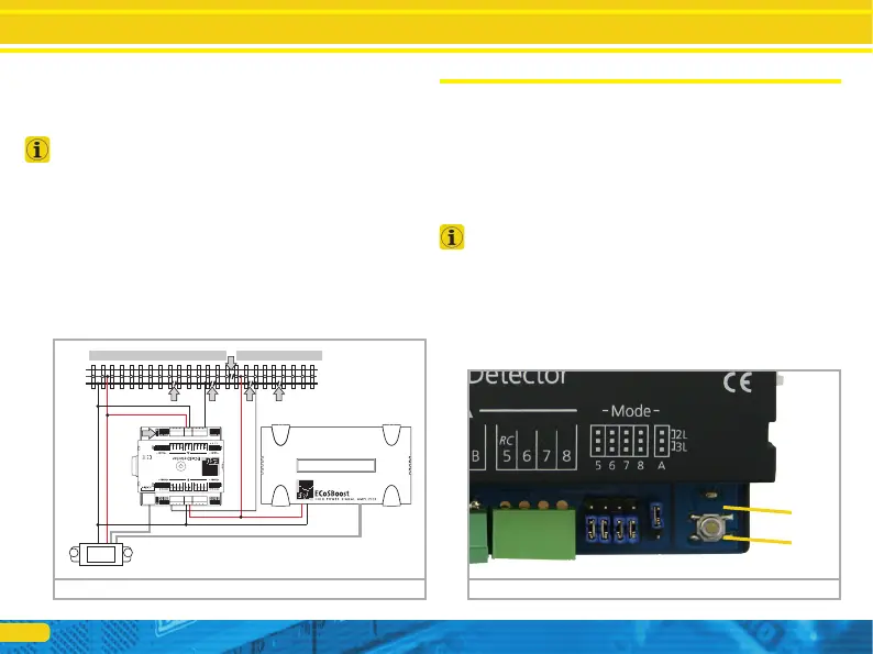
6.4. Two booster sectors on one ECoSDetector
The feedback inputs of the ECoSDetector are divided into two
groups: “A” (inputs 1 through 8) and “B” (inputs 9 through16).
These two groups can be supplied by two different booster sec-
tors. Each feedback group has terminals “B” and “0” to be con-
nected to the booster outputs that supplies power for the track
sector to be monitored. In figure 9 we show an example of how
to wire a 3-rail system where both feedback groups receive power
from their own separate power supply (group “A” form the ECoS
and group “B” from a separate ECoSBoost.
Connecting to the command station
7. Connecting to the command station
The ECoSDetector is wired with the supplied ECoSlink cable direct-
ly to one of the three ECoSlink sockets of your ECoS. The power
supply for each ECoSDetector is provided by the ECoS command
station. To which socket you connect which ECoSDetector has no
relevance regarding the internal numbering sequence of the feed-
back inputs. After connecting it each ECoSDetector is automati-
cally detected by the command station and linked to the system.
To be able to utilize the feedback inputs successfully you only have
to set a few things in the setup menu on the command station.
If you wish to use more than three ECoSDetector modules or if
the supplied cable is too short you should extend the ECoSlink bus
with the aid of the ECoSlink-Terminal (ESU part number 50099).
The bus can be extended up to 100 meters. Due to the bus topo-
logy an extension of the supplied ECoSlink cable is not possible!
After connecting the ECoSDetector successfully the status LED a)
must be lit continuously. The button b) can be used for easy iden-
tification of the ECoSDetector module.
B
0
B0
ECoS ECoSBoost
5678
Figure 9: 3-rail layout with two booster sections Figure 10: LED a) and button b)
a)
b)