7
The occupancy feedback will work trouble free if the track sector
to be monitored has been isolated at both ends.
Do not forget to set the jumpers of the ECoSDetector correctly.
This is not necessary with the ECoSDetector Standard.
Please keep the wiring between the feedback module and the
track sector to be monitored as short as possible. If the wires
are very long and installed close to each other it may result in an
unintentional data transfer between the wires. Even though only
one track sector is occupied several feedback inputs may report
“occupied”.
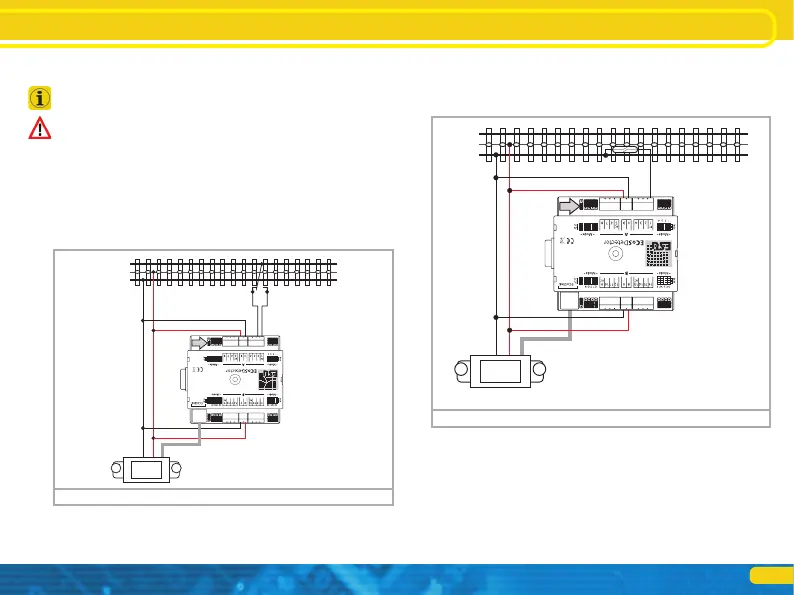
6.1.3. Track switches
Figure 3 shows how to connect a Märklin® track switch. Please
note that this track switch functions directionally!
Connecting it to the tracks
Figure 3: How to connect a track switch
B
0
5678
Connecting it to the tracks
6.1.4. Reed contacts
Figure 4 shows how to wire a reed contact. Please make sure that
you install sufficiently strong magnets at the underside of your
vehicles to assure reliable function even at high speeds!
6.1.5. Externally supplied switches
The ECoSDetector also works without direct connection to the
track by means of commercially available switches or push but-
tons. In this case you must supply the ECoSDetector with a DC
voltage (!) ranging between 12V and 22V. Figure 5 shows how
it is done:
B
0
5678
Figure 4: Connection of a reed contact to an outer conductor