6
6. Connecting it to the tracks
In this paragraph we show you how to wire the ECoSDetector
module to the tracks. In the figures the ECoSDetector module is
shown; wiring the ECoSDetector Standard is identical. However,
on the ECoSDetector Standard there are no jumpers.
6.1. Common contacts
As feedback inputs configured as common inputs you may con-
nect all contacts that switch the input to the common conductor
(often this is the “brown“digital feeder). Thus you can switch eit-
her against the terminal marked as “0” or against the terminal 0
(brown) at the track.
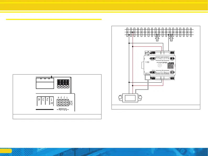
6.1.1. Jumpers
The ECoSDetector has a jumper for each feedback input for confi-
guring the input either as common contact or as current sensor.
6.1.2. 3-rail track system (contact track section)
Figure 2 shows how to wire a contact track in a 3-rail system.
• Wire the inputs „0“and „B“of the ECoSDetector with the approp-
riate booster output. In example 2 both feedback groups “A” and
“B” are supplied from the same booster. Therefore the terminals
“0” and “B” on both sides of the ECoSDetector must be connec-
ted with each other. If you use a separate booster for the inputs of
group “B” (feedback inputs 9 through 16) the ECoSDetector has
to be wired as described in chapter 6.4.
• Connect the insulated sector of the track to be monitored to one
of the input terminals “1” to “16” of the ECoSDetector module.
Figure 1: „Jumpers“
Connecting it to the tracks
Figure 2: 3-rail track system as contact track
B
0
5678
If you wish to use the input as common contact place the corres-
ponding jumper to the outer position “3L”. In figure 1 all inputs
are configured as common contacts. But, of course, you may con-
figure each input individually.