9
Connecting it to the tracks Connecting it to the tracks
Otherwise a short circuit would occur every time a locomotive or
car bridges the gap between different sectors.
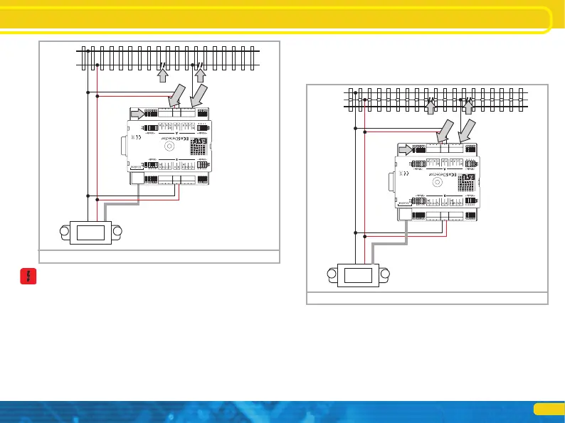
6.2.3. 3-rail track system
The current sensor mode is also recommended for the 3-rail track
system. Cut the centre conductor of the track sector to be moni-
tored at both (!) ends and connect it to the feedback input of the
ECoSDetector.
• Connect the inputs „0“and „B“of the ECoSDetector with the ap-
propriate booster output. In the example shown in figure 8 both
feedback groups “A” and “B” are supplied by the same booster.
Therefore the terminals “0” and “B” on both sides of the ECoS-
Detector must be connected with each other. If you use a separate
ECoSBoost for group “B” (feedback inputs 9 through 16) then the
module must be wired as described in chapter 6.4.
• Connect the feedback terminals “1” through “16” with the cor-
responding track sector (isolated centre conductor) which must be
insulated from the rest of the layout at both ends (!).
Figure 8: 3-rail track system current sensor
B0
RailCom
RailCom
5678
5678
B0
RailCom
RailCom
Figure 7: 2-rail track system current sensor
6.3. RailCom® feedback (no for ECoSDetector Standard)
In addition to the conventional occupancy feedback (“track occu-
pied” or “track unoccupied”) the inputs 1, 5, 9 and 13 can read
out the address of the locomotive locate on this particular track
sector. A pre-condition for this mode is that the locomotive deco-
der supports RailCom® or RailComPlus® and that this function is
also activated in the decoder. Only then the locomotive decoder