8
Connecting it to the tracks
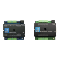
Please note that the jumper for the power supply (marked with an
arrow in figure 5 at the top left) must be set to the outer position
for this operating mode.
6.2. Current sensor (not for ECoSDetector Standard)
Each of the 16 feedback inputs of the ECoSDetector can be confi-
gured as current sensor. This is the most reliable type of feedback
and is suitable both for 3-rail systems and 2-rail systems.
If you have a choice (whenever you rewire your layout), select the
current sensor option since the feedback function is far more reli-
able than the known common contacts.
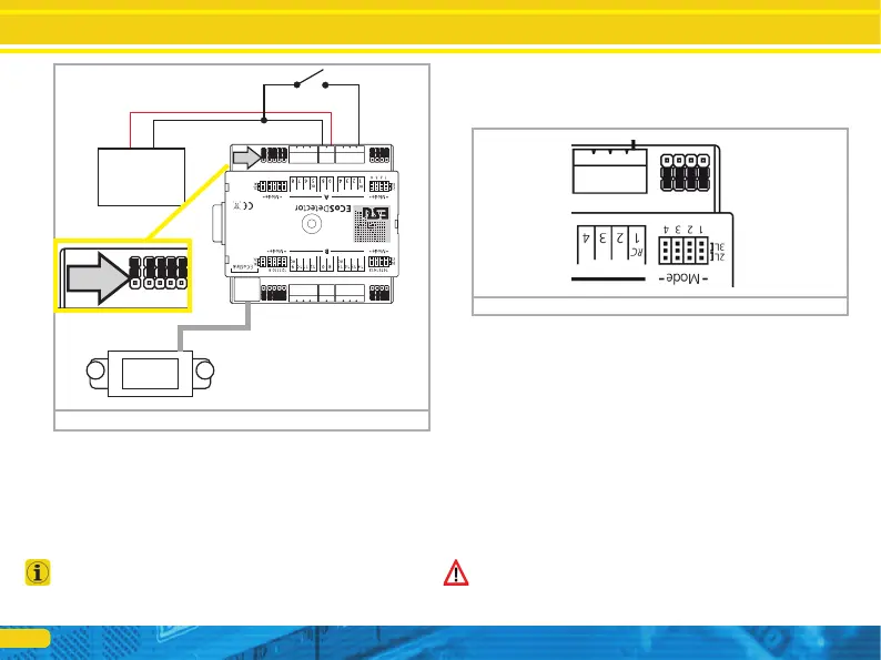
6.2.1. Jumpers
The ECoSDetector has a jumper for each feedback input in order
to configure this input either as common contact or as current
sensor.
If you wish to use an input as current sensor place the jumper
onto the inner position “2L”. In figure 6 the inputs 1 to 4 are
configured as current sensors. But, of course, you can configure
each input individually.
6.2.2. 2-rail track system
• Connect the inputs “0” and “B” of the ECoSDetector with the ap-
propriate booster output. In the example in figure 7 both feedback
groups “A” and “B” are supplied by the same booster. Therefore
the terminals “0” and “B” on both sides of the ECoSDetector
must be connected with each other. If you use a separate ECoS-
Boost for group “B” (feedback inputs 9 through 16) then the mo-
dule must be wired as described in chapter 6.4.
• Connect the feedback terminals “1” through “16” with the cor-
responding track sector which must be insulated from the rest of
the layout at both ends (!).
Please make sure that you always cut the “correct” track and thus
the correct pole of the digital track voltage when isolating the track
sectors. In figure 7 it is shown that the conductor “B” (red) must be
isolated. This must be done in the same way for the entire layout.
Figure 6: „Jumpers“
DC
12-22Volt
+-
5678
Figure 5: Operation with common rocker switches