13
Wiring the outputs
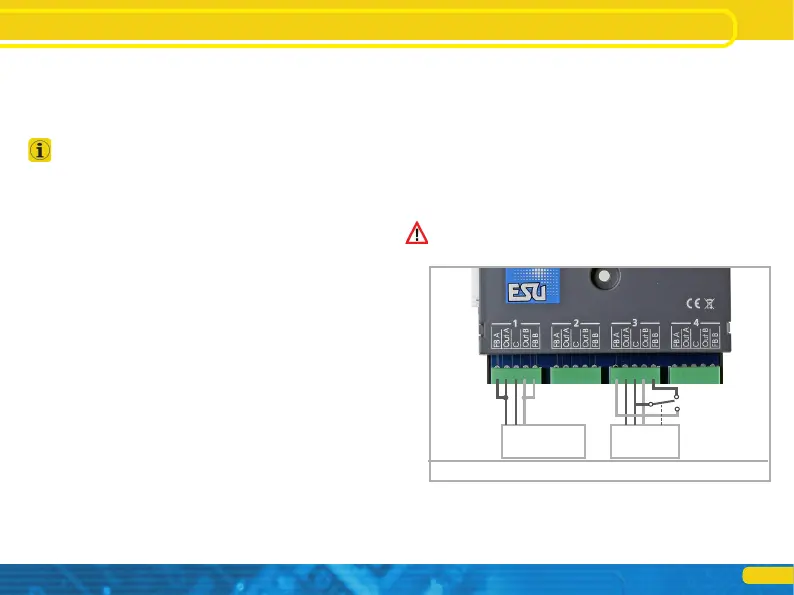
If, on the other hand, signals or lighting with LEDs are used (as
shown in Figure 8, Output 3), a series resistor must be used to
limit the current. The resistance value depends to a large extent
on the type of LED used, so no precise statement is possible here.
Values between 1 kOhm and 10 kOhm are common. If in doubt,
start with a higher value.
The terminal C of the output is the „+” pole. Therefore, the catho-
de of the LED must be connected to the terminals Out A or Out B.
5.4.3. Uncoupling tracks
The momentary action mode is suitable for uncoupling tracks, as
the coil will be active only until the button is released. The wiring
is as shown in Fig. 8, Terminal 4. You can use either Terminal Out A
or Out B, depending on whether you want to activate the uncoup-
ler with the „diverging” or „straight” turnout button.
b)
or
a)
Figure 9: Connection of the turnout feedback
5.5. Wiring the feedback contacts
The SwitchPilot 3 can report the actual turnout status to the ESU
ECoS command station via RailCom®. For this purpose, however,
the turnout must have appropriate mechanical feedback contacts.
Figure 9 illustrates the scenario.
a) Connection of a turnout drive with limit stop contacts. Con-
nect terminals Out A to FB A and Out B to FB B.
b) Connection to drives with separate feedback contacts: Here
you wire the two feedback contacts to the terminals FB A and
FB B respectively, and the common wire of the feedback to
terminal C.
You will find more information on turnout feedback to the ESU
ECoS via RailCom® in chapter 11.
 Loading...