14
5.6. Connecting the SwitchPilot Extension
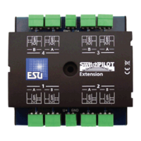
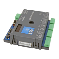
The SwitchPilot Extension module is docked sideways to the
SwitchPilot 3; press the extension module with the 8-pin plugs
against the SwitchPilot 3 until the retaining clips of the plugs snap
in. The internal electronics and relay coils of the SwitchPilot Exten-
sion module are powered by the SwitchPilot 3.
5.6.1. Relay outputs
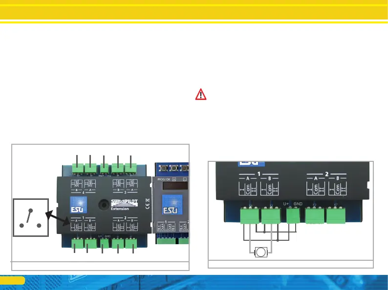
Fig. 10 shows the connections:
a) The outputs 1 to 4 are connected to relay outputs A and B,
which are activated jointly (2x change-over contacts, bistable).
Each relay output corresponds to the corresponding transistor
output of the SwitchPilot 3. If the output Out A of the Switch-
Pilot 3 is active, the terminals I and COM of the relay output
are also active. If the output Out B on the SwitchPilot 3 is
active, terminals II and COM are also active.
b) Terminals for ground and „U+” (rectified track voltage, sup-
plied by SwitchPilot 3) for powering DC turnout motors.
5.6.2. Motorized turnout drives
Motorized turnout drives can be controlled with the help of the
SwitchPilot Extension module. Reversing the operating voltage of
the electric motor changes the direction of rotation of the mo-
tor, thereby moving the turnout from one position (status) to the
other.
Use only turnout drives with limit stop contacts to prevent the
motor from burning through, because the relay outputs of the
SwitchPilot Extension module are continuously active.
The wiring of the motorized turnout drive is shown in Fig. 11.
Please note the maximum supply voltage values specified in the
instructions for your drive. The Extension module always delivers
the full voltage that is provided to the SwitchPilot 3.
Figure 10: SwitchPilot with mounted SwitchPilot Extension
a) a)
b) a) a)
a) a)
b) a)
a)
I
II
Com
Figure 11: Motorized point machine with SwitchPilot Extension
M
Wiring the outputs


 To Next Page