Configuration parameter [Buffer] function block
6.2 [Buffer] function block
6.2.1 Basic settings
Basic buffer settings
Set or check the following parameters.
Detailed descriptions of the parameters are provided
below.
Explanation of [Buffer top min.]
This parameter defines the minimum temperature of
the buffer storage tank inside the configured time slot.
The factory setting for this parameter is 10°C.
The higher this temperature is set, the larger the
heat reserve in the buffer. At the same time, however,
higher temperatures in the buffer reduce the solar
yield. Because the buffer is kept at the [Buffer top min.]
temperature using energy from the boiler, even if there
is no demand from the consumers.
The factory setting can remain unchanged as long as
all components of the heating system are controlled by
the ETA control system. A higher value is required if
peaks in output have to be covered or very fast heat
availability is needed.
Explanation of [Hysteresis top]
The target temperature of the buffer [Buffer target] is
calculated from the current requirements of the
consumers and the [Buffer top min.]. This temperature
is additionally increased by the set value [Hysteresis
top], and this is then the new target temperature for the
buffer.
This limits short boiler cycles (continuous
switching on and off), and so increases the boiler
runtime.
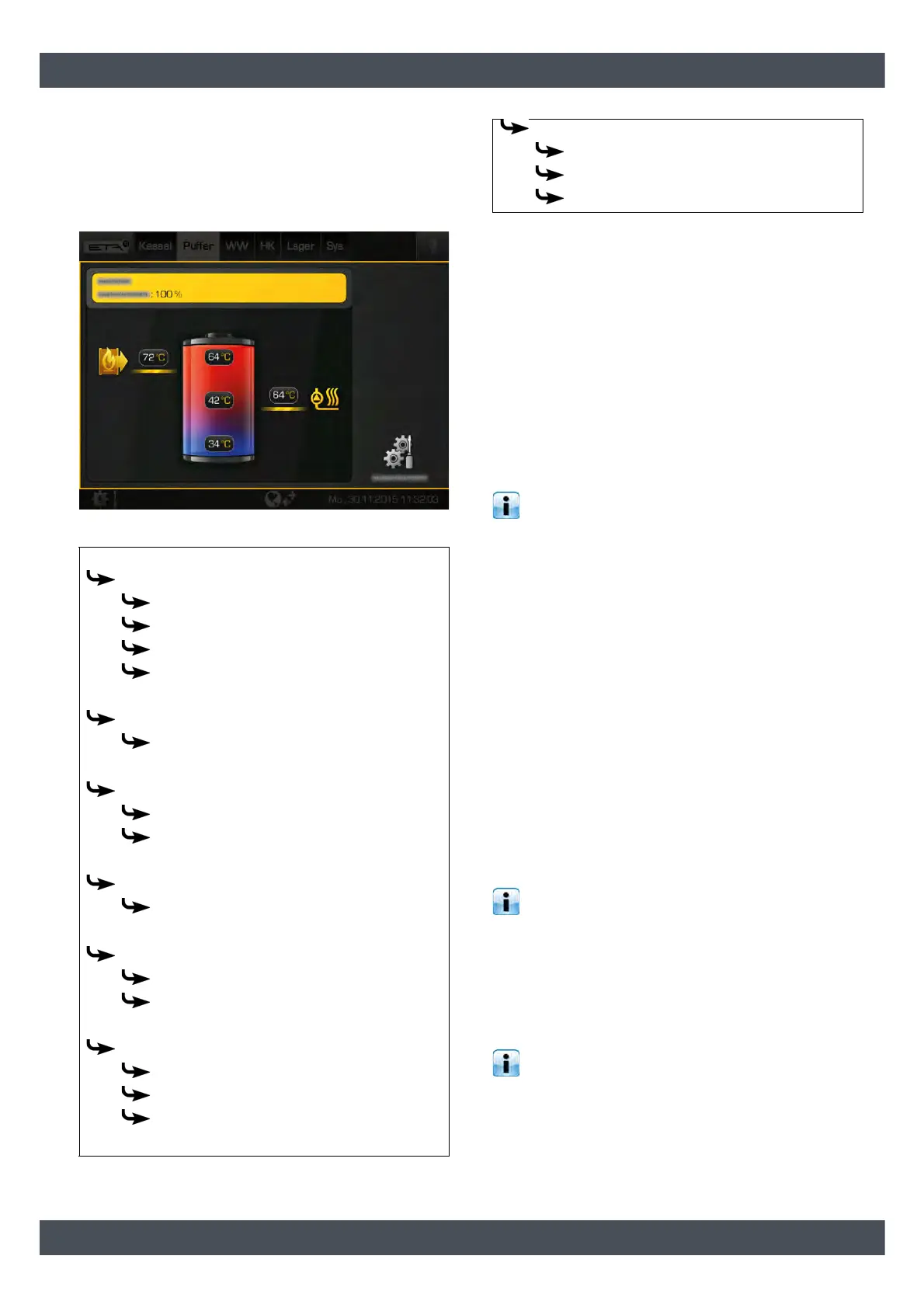
Example:
Temperature demanded by the consumers = 64 °C
[Hysteresis top] = 6 °C
=> Target temperature of the accumulator tanks
[Buffer target] = 70 °C
In systems with low consumer temperatures
(underfloor heating only, for example), the
hysteresis can be increased. In systems with high
consumer temperatures, the hysteresis can be
reduced.
Buffer
Buffer top
Buffer top min.
Hysteresis top
Flow temp raise
Enable temperature
Buffer top/middle
a
Chrg. at buffer top/middle
Buffer middle
b
Chrg.at buffer middle
Switch off at buffer middle
Buffer middle/bottom
c
Switch off at buffer middle/bottom
Buffer bottom
Buffer bottom off
Enable difference
demanded output
b
Effective buffer volume [l]
Desired charging time
Return from consumers
Extra charge
Buffer top min.
Buffer bottom off
Extra charging from
a. Only visible with additional temperature sensor [Temp.
sensor at buffer top/middle]
b. Only visible with additional temperature sensor [Temp.
sensor at buffer middle]
c. Only visible with additional temperature sensor [Temp.
sensor at buffer middle/bottom]