BM04101 Molift Quick Raiser English - Rev F/ 09/2012 Page 8 of 20
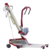
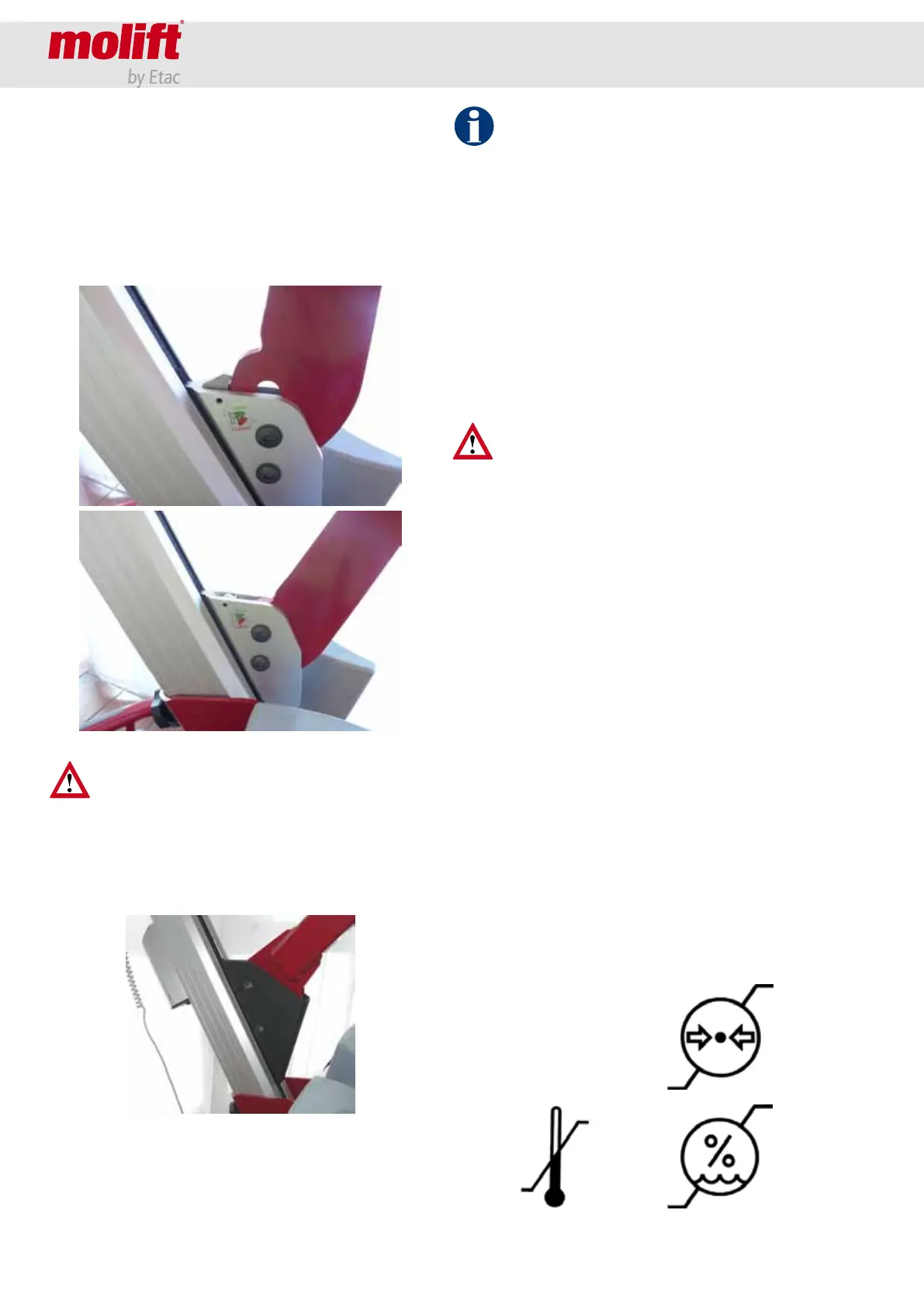
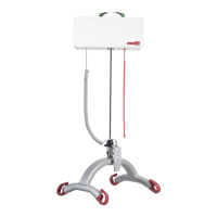
• Attach the lifting arm to the trolley on the col-
umn.
QR1 and QR2: On the trolley there is a small safe-
ty lock which has to be pushed up to ensure
a correct attachment of the lifting arm on the
trolley. Open the safety lock and then guide
the arm in place over the two bolts in the trol-
ley. Lock the safety lock by pushing it down.
Be careful not to put fingers or similar under
the lifting arm between arm and trolley. Dan-
ger of personnel injury.
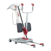
QR2+: Place the lifting arm, install the bolt and
attach with the screws. Torque 28 Nm. Secure
screws with Loctite 2701.
• Place the battery in the battery holder with the
connectors facing down. Run each function of
the lifter a couple of times without load to veri-
fy that the lifter works.
0°C
45°C
Molift Group AS,
Ole Deviksvei 44,
0668 Oslo
Norway
(+47) 4000 1004
www.molift.com
20 %
90 %
50 kPa
106 kPa
Labeling outside on every cartoon with Molift lifter or accessories/spare parts
Size on label ca 105x75 mm
Black printing directly on cartoon
Alternatively the labels can be printed on a A4 8 labels sheet (black printing on white bacground).
Note! Only page 2 for printing on sheet with 8 labels
Desctiption Dimension Material Comment
Designed/Drawn
I. Værnes
Date
14.11.07
Projection Scale
Drawing name
Label packing
Storage conditions
Drawing
1
Size
A4
A Released for production 14.11.07 IV
Rev Description Date/Sign Approved
Etac Supply Gjøvik tests all lifters with and
without load before shipment. The control is
an extra precaution to uncover any shipment
damage and/or incorrect assembly.
Checklist
• Verify that the lifting arm is properly fastened
to the trolley.
• Verify that the lifting column is properly placed
into the chassis - arrow shall be exactly aligned
with the edge of the chassis.
• Verify that the column is properly fastened
with bolts tightened.
Make sure that the lifter has no damage or
cracks, and that the lifting arm and column is
properly fixed before use!
Disassembly
• Remove the battery.
• Remove the lifting arm by opening the securi-
ty lock on the trolley at then pull out the lifting
arm.
• Loosen the lock wheel for the drive handle and
pull the handle with plate and locking wheel
up and out of the column.
• Remove the locking wheel for the knee sup-
port and remove the complete knee support
(also possible to leave on the column). Replace
the locking wheel on the bolt on column to
avoid it from getting lost.
• Loosen the column xing bolts with Allen key
and lift out the column.
Storage
For long time storage it is recommended that the
battery is removed and the emergency stop but-
ton is activated. Storage conditions should be be-
tween
Pressure: 50 - 106 kPa
Humidity: 20 - 90 %
Temperature: 0 - 45 °C