9
2084606-19-09/17 (translation of the original operating instructions)
Operating Instructions
Non-Contact Safety System CES-A-AEA-02B/CES-A-AEA-04B
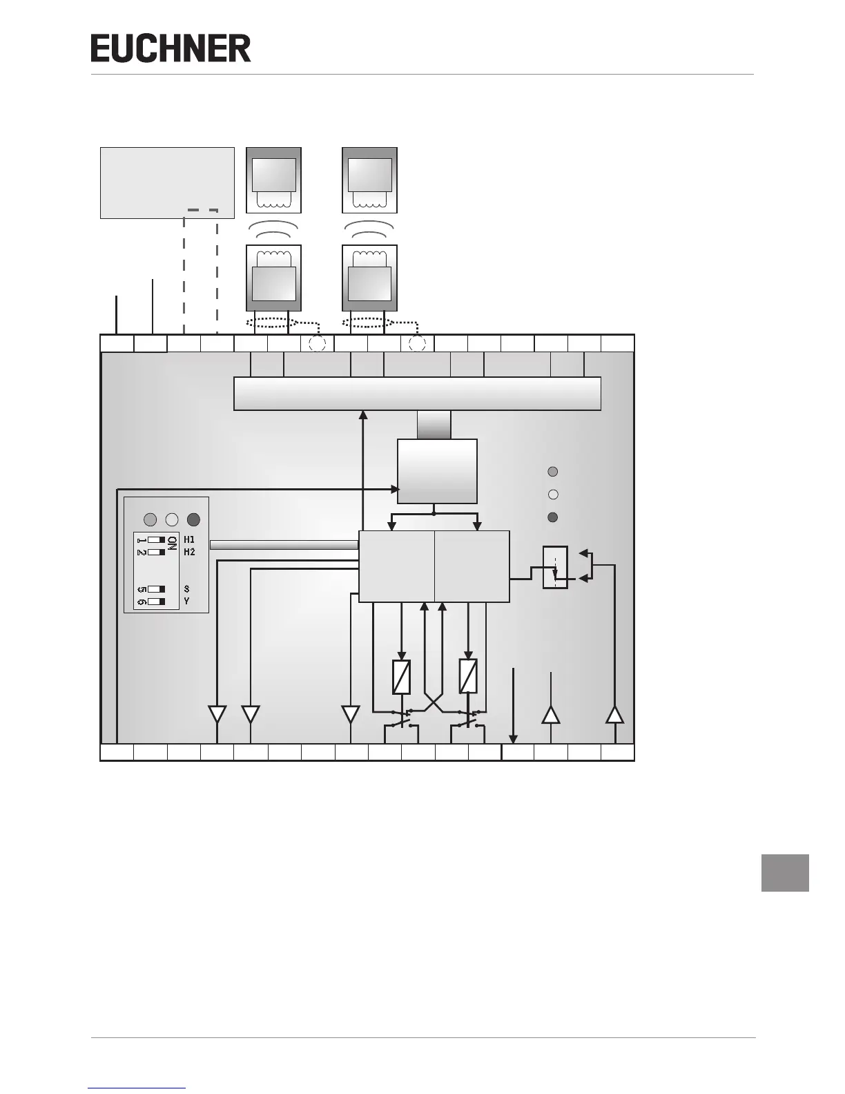
6.1. Block diagrams CES-A-AEA-…
CES-A-AEA-02B
Trans-
ponder
Trans-
ponder
Kopf 1 Kopf 2
A B
0 V
UB
TST
0V
S
H11 H21H12 H22SH1 SH2
DIA
14
1323 Y1
24 Y2
Demodulator
Filter
Verstärker
Komparator
KA
KB
Kopf - HF - Multiplexer
( 1 aus 4 )
J2
J1
O1 O2
+24 V
KA
KB
CPU-A
(Typ 1)
LED
STAT E
OUT
DIA
Star t
CPU-B
(Typ 2)
STATEOUT DIA
Y
S
H2
H1
ON
1 2
5 6
Activation of the
teach-in operation with
jumper
on J1, J2
Read heads
Coded
actuators
Trans-
ponder
Trans-
ponder
Head 1
Head 2
DC
+ 24 V
Operating
voltage
Demodulator
Filter
Amplifier
Comparator
Head selection
CPU-A
(type 1)
Head - RF - multiplexer
(1 of 2)
CPU-B
CPU-B
CPU-A
CPU-A
Start
CPU-B
(type 2)
DIP switch
+UB, 0 V Power supply
J1, J2 Jumper for teach-in operation
H11/H12/H21/H22 Connection for read heads 1 ... 2
SH1, SH2 Shield
TST Test input (see chapter 9.3.1. Self‑test with test input TST on page 16)
O1 ... O2 Semiconductor monitoring outputs
DIA Diagnostic output
13, 14 Connection for relay contact A, safety relay enable
23, 24 Connection for relay contact B, safety relay enable
Y1, Y2 Feedback loop
S Start button connection (monitoring of the falling edge)
 Loading...