13
Operation and Maintenance Instructions
At initial start up or after the unit has been drained, the unit must be filled to the overflow level. Overflow is above the normal
operating level and accommodates the volume of water normally in suspension in the water distribution system and some of the
piping external to the unit.
The water level should always be above the strainer. Check by running the pump with the fan motors off and observing the water
level through the access door or remove the air inlet louver.
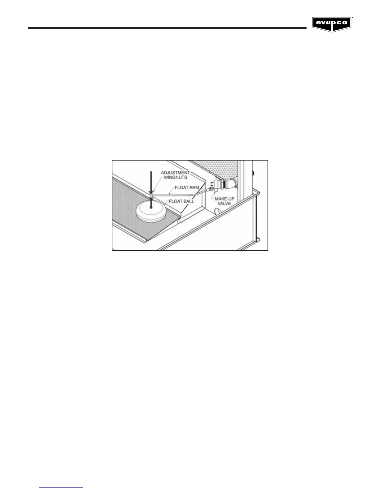
Water Make Up Valve
A mechanical float valve assembly is provided as standard equipment on the evaporative cooling unit (unless the unit has been
ordered with an optional electronic water level control package or the unit is arranged for remote sump operation). The make up
valve is easily accessible from outside the unit through the louver access door or removable air inlet louver. The make up valve is a
bronze valve connected to a float arm assembly and is activated by a large foam filled plastic float. The float is mounted on an all
thread rod held in place by wing nuts. The water level in the basin is adjusted by repositioning the float and all thread using the
wing nuts. Refer to Figure 9 for details.
The make up valve assembly should be inspected monthly and adjusted as required. The valve should be inspected annually for
leakage and if necessary, the valve seat should be replaced. The make up water pressure should be maintained between 20 and
50 PSIG.
Pressurized Water Distribution Systems
All EVAPCO cooling towers are supplied with wide orifice water diffusers. The water distribution system should be checked monthly
to make sure it is operating properly. Always check the spray system with the pump on and the fans off (locked and tagged out).
On forced draft units (LSTB, LPT and LSTA models), remove one or two eliminator sections from the top of the unit and observe
the operation of the water distribution system.
On induced draft units (AT, USS, UT and ICT models), lifting handles are provided on several sections of eliminators within reach of
the access door. Eliminators can be easily removed from outside of the unit to observe the water distribution system. The diffusers
are essentially non-clogging and should seldom need cleaning or maintenance.
Figure 9 – Mechanical Water Make Up Valve
 Loading...