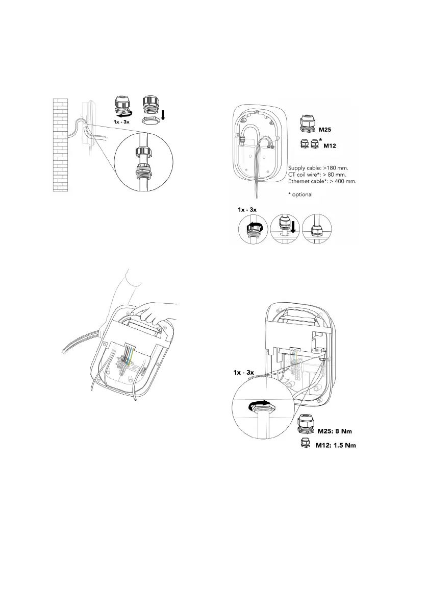
39
a. Remove the lock nuts from the cable
glands and mount the cable glands on the
power supply cable and (optionally) on the
CT coil cable and Ethernet cable with their
sealing nuts on the outside of the wallbox.
b. Insert the supply cables from the back of
the wallbox through the cable opening
of the main assembly.
c. Make sure the following lengths of cables
are available after the cable glands, then
tighten each cable gland.
› Power supply cable: > 180 mm.
› CT coil cable (optional): > 80 mm.
› Ethernet cable (optional): > 400 mm.
d. Secure the cable glands by tightening
their lock nuts.