49
Set DIP-switches
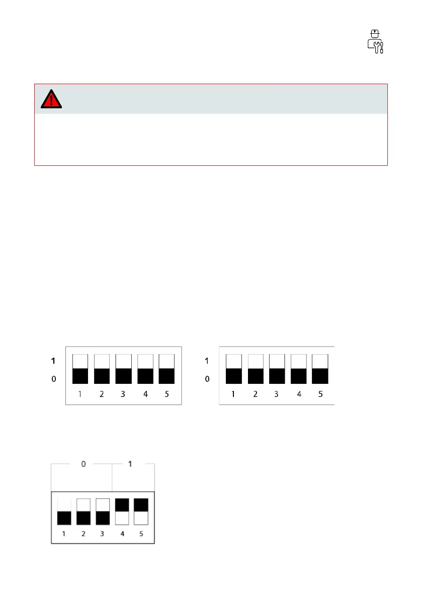
The power board has two groups of 5-pin DIP-switches:
› Group A determines the coil type used for
the current transformer and denes the
ground loss monitor functionality.
Example of DIP-switch setting: 0, 0, 0, 1, 1
In the following illustrations and tables, the upper switch position is being referred to as
position 1, whereas the lower switch position is being referred to as position 0.
DIP-switch positions:
› Group B determines the maximum availa-
ble current of the facility/house, or of the
wallbox itself, depending on the group A
conguration.
GROUP A
CT-TYPE
P LIM
GROUP B
The Overload Protection feature of the Audi Wallbox enables use of as much power of the
installation as possible at any given time. For more information, see chapter Overload
Protection.
Danger
Not following the instructions given in this document will result in the risk of electric shock
to users, which will cause severe injuries or death.
› The installation must only be performed by certied electricians, who can correctly and
safely install the wallbox and identify potential danger.