58
English
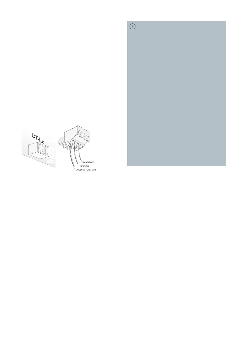
e. Connect the data cable’s EMC shield
to the MCVR 1.5/3-ST-3.81 connector
using the data cable’s drain wire. Alter-
natively, use a shield connector.
Make sure that the EMC shield will
therefore be connected to the left pin of
the Audi Wallbox's female PCB connec-
tor for proper grounding.
f. Connect the MCVR 1.5/3-ST-3.81 con-
nector to the female PCB connector on
the Audi Wallbox's power board.
The gure hereafter is showing the
installation slots of the MCVR 1.5/3-ST-
3.81 connector with respect to the female
PCB connector on the Audi Wallbox's power
board.
Conguration of Elli Charger for Overload
Protection
For further details refer to chapter Set DIP-
switches.
5. Set the Audi Wallbox's DIP-switches in
order to congure the Overload Protec-
tion parameters.
a. Set the DIP-switches 1-4 of Group A in
order to select the CT coil model used.
b. Set the DIP-switches of Group B in
order to select the max. facility current
allowed at the CT coil’s place of installa-
tion.
c. Optionally, in case of an Audi Wallbox
plus or pro, use the Conguration Mana-
ger to conduct further CT coil settings.
d. Optionally, in case of an Audi Wallbox
plus or pro, use the Conguration
Manager to double check the correct
Overload Protection conguration.
The relative deviation of the current
measurement using CTs of Elli Charger’s
Control System is 6%. This deviation
is automatically taken into account by
the Audi Wallbox's Control System of
the models Audi Wallbox plus and Audi
Wallbox pro.
No further precautions need to be taken
when setting the DIP-switches and the
congured maximum facility current. For
the model Audi Wallbox, it depends on
the material number, which can be found
on the packaging label of the housing. For
the material numbers 200001, 200002,
200251 and 2002522, this deviation is
NOT automatically taken into account by
the Audi Wallbox's Control System.
This deviation needs to be taken when set-
ting the DIP-switches and the congured
maximum facility current.
For any other material number, no further
precautions need to be taken when setting
the DIP-switches and the congured maxi-
mum facility current.