7
HOMEDEPOT.COM
Please contact 1-844-883-1872 for further assistance.
Electrical Settings
WARNING: Disconnect power before working on the pump, motor, pressure switch, or wiring.
CAUTION: The motor may b
e hot. Allow the motor to cool for 20 minutes after shut down.
CAUTION: Water pressure may have built up in the pump, pipes, or tank. Drain water to relieve pressure.
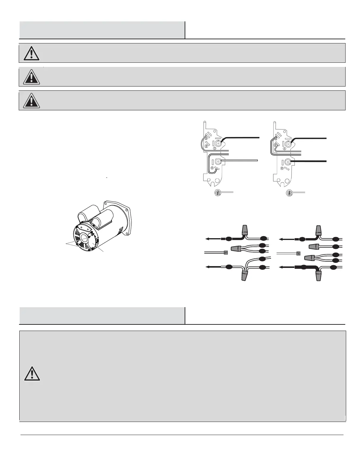
Wiring Connections
P
late Screws
Motor Cover Plate
WARNING: Risk of el
ectric shock. Can shock, burn, or kill.
1. To avoid dangerous or fatal electrical shock, turn OFF power to the motor before working on electrical
con
nections.
2. Grou
nd the motor before connecting to electrical power supply. Failure to ground the motor can cause severe or
fatal electrical shock hazard.
3. Supply voltage must be within +/- 10% of the nameplate voltage. Incorrect voltage can cause fire or damage the
motor and voids the warr
anty. If in doubt consult a licensed electrician.
4. Use a
wire size specified in the Wiring Chart (below). If possible, connect the pump to a separate branch circuit
with no other appliances on it.
5. Do not ground to a gas suppl
y line.
6. Wire the motor according to the
7. If the diagram
on the motor cover plate differs fr om the diagrams in this section, follow the diagram on the
8.
If this procedure or the wiring diagrams are confusing, consult a licensed electrician.
diagram on the motor cover plate.
motor cover plate.
T4
T2
T3
P2
P1
T2
T3
P1
L1
TO BREAKER BOX
HOT
NEUTRAL
TO BREAKER BOX
L2
L1
P2
T4
TO BREAKER BOX
HOT
TO BREAKER BOX
GROUND WIRE
HOT
GROUND WIRE
115V 60Hz
230V 60Hz
Wiring Diagram for EFLS10-HD
Wiring Diagram for EFLS15-HD and EFLS20-HD
L2
MOTOR VOLTAGE SETTINGS
Motors are designed to run on
either 115 volt or 230 volt power.
Ensure the motor’s wiring is set to match the voltage being
supplied to your motor from the electrical source.
WHITE
115V 60Hz
LINE 1
To Breaker
LINE 2
To Breaker
Hot
Neutral
BLUE
GROUND
GREEN
LINE 1
To Breaker
LINE 2
To Breaker
Hot
Hot
230V 60Hz
WHITE
BLUE
GROUND
GREEN
WIRING THE PUMP FOR THE INCORRECT VOLTAGE WILL
end cover. Wire the pump according to the diagram to the right.
Remove the plate screws and the motor cover plate from the motor
DAMAGE THE PUMP.