65
Electrical System
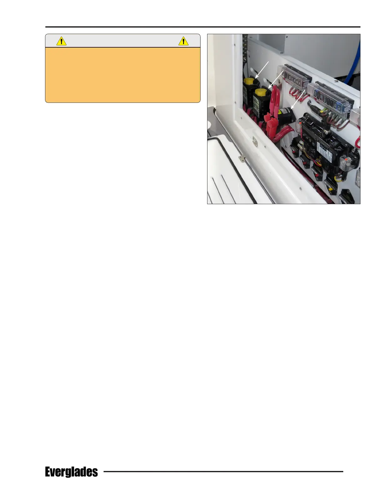
Starboard Engine & House Battery Switches & Parallel Relay
On Fuse and Breaker Panel In The Battery Compartment
NEVER USE WET CELL BATTERIES. THE BATTERY
COMPARTMENT BELOW THE HELM SEATS IS NOT DESIGNED
FOR WET CELL BATTERIES. WET CELL BATTERIES WILL EMIT
DANGEROUS HYDROGEN GAS INTO THE COMPARTMENT
DURING CHARGING THAT COULD ACCUMULATE AND
EXPLODE CAUSING SEVERE INJURY TO PASSENGERS AND
DAMAGE TO THE BOAT.
Use only marine AGM batteries. Never use gel cell or
lithium batteries. The engine charging system and/
or the battery charger may not be able to recharge
gel cell or lithium batteries properly which could
cause unusually short battery life, engine starting
problems and damage to the DC charging systems.
You also should not mix the size or brand of batter-
ies. Always consult your dealer before changing the
type of batteries in your boat.
The engine starting batteries should be of the size
and capacity recommended by the manufacturer of
your engines. These specications should be con-
sidered the minimum size battery required. Consider
increasing the capacity of the batteries if you will be
trolling, drift shing or have extensive electronics
on board. Larger batteries will give you additional
capacity to operate the baitwells, DC accessories,
the optional Seakeeper and electronics at low speed
when the charging system output from the engines
is minimal. Refer to the engine owner’s manual for
additional information on the battery requirements
for your engines.
Battery Switches
Your boat is equipped with 4 batteries. One battery
for each engine and two batteries wired in parallel
for the house.
There is a remote activated battery switch for each
engine and one for the house circuits located on the
fuse and breaker panel. The battery parallel relay
and other relays are activated by dedicated switches
in the Garmin display panel.
Each battery switch has a manual override that can
activate (enable) or deactivate (disable) the switch
if the remote switch or relay fails. The manual over-
ride is a yellow knob on each switch that can be
pressed to manually activate the switch or rotated
to reactivate remote activation of the switch or to
lockout the switch in the OFF position when servicing
the electrical system. The normal operating position
for each switch is the “Enabled” Position. Refer to
the instructions printed on each switch and/or the
battery switch operation manual for additional infor-
mation on the remote activated switches.
Automatic Charging Relays (ACR) control the charg-
ing of the engine and house batteries whenever
the engines are operating. The engine and house
batteries are also charged by the battery charger
whenever it is activated.
The ACR systems manage the charging current for
the 12 volt system whenever the engines are run-
ning. The systems automatically sense the condi-
tion of each battery and direct the available current
to the batteries that require charging. When the
engines are started, the engine alternators start to
recharge the batteries. This charging current passes
through the ACR sensing circuits. The circuits sense
the charge and it is split between the batteries, with
the lowest battery receiving the most charge. When
the engines are turned o, charging stops and the
sensing circuit turns o each ACR, disconnecting
the batteries from the charging circuit, thereby au-
tomatically isolating the batteries from one another.
When in port or at anchor, the engine battery
switches should be o. Only the battery switch
that activates the House circuits should be on. This
will keep the engine starting batteries in reserve for
starting the engines.