67
Electrical System
6.6 Ignition Switch Panels
Ignition Switch Panels
Ignition switch panels are unique to each engine
manufacturer and the engine control options
selected. Your dealer will provide you with the
proper starting procedure for your boat at the time
of delivery. Additional information for the ignition
switch system installed in your boat is located in
the engine and control system operating manuals
included in your information packet.
The following instructions is an overview for
typical Mercury and Yamaha ignition switch pan-
els commonly installed on Everglades boats. Your
boat may be dierent depending on the options
selected.
Standard Ignition Switch
The ignition switches are key activated switches
located at the helm or on the aft head compart-
ment bulkhead which start and stop the engines.
Most switches have OFF-ON and momentary
START positions. Some switches also have an ACC
position to activate selected 12 volt equipment
without energizing the engine ignition circuits.
To start the engines, make sure the engines are
down with the shift levers in the neutral position
and your hand is on the control levers. Turn the
ignition key for the port engine to the START posi-
tion briey, then release the key. The computer will
automatically check all engine systems and start
the engine. When the engine stabilizes, repeat the
starting procedure for the starboard engine. Stop
each engine by turning the key switches to the OFF
position.
The ignition circuit is protected by a circuit breaker
located in the battery switch panel and/or fuses
located on the engine.
Mercury Digital Ignition
Mercury digital ignition panels are equipped with
ON/OFF key switches located on the aft head com-
partment bulkhead and a START/STOP panel at the
helm or built into the engine controls.
The Start/Stop panel is used in conjunction with
the key switches and features a START/STOP but-
ton for each engine. This system greatly simplies
the starting and stopping process of your engines.
For convenience and protection, engines can not
be restarted while running.
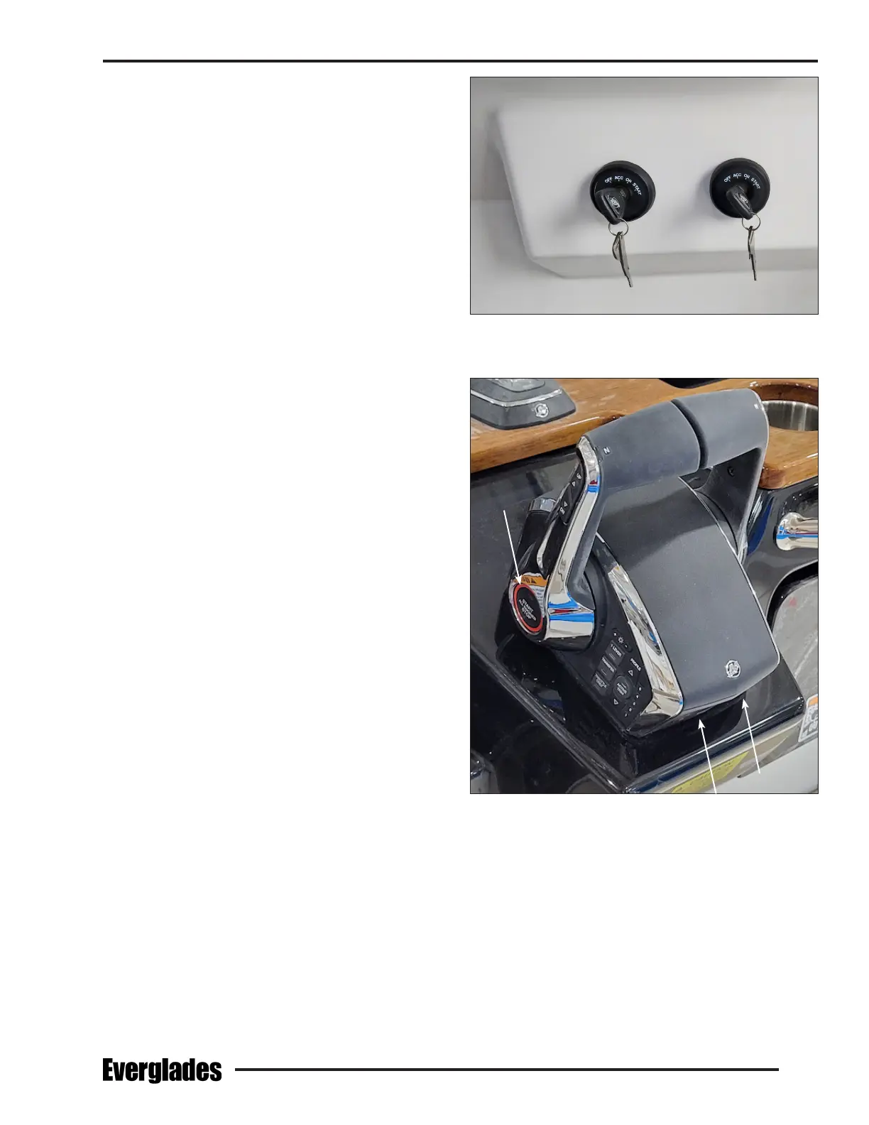
Typical Mercury Ignition Switches
On Aft Head Compartment Bulkhead
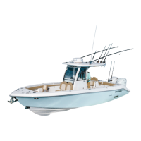
Mercury Control Engine Start/Stop Buttons
Starting Procedure
Turn each ignition key to the ON position to activate
the START buttons for both engines. Make sure the
engines are down with the shift levers in the neutral
position and your hand is on the control levers.
Press and release the START/STOP button for the
port engine. The computer will automatically check
all engine systems and start the engine. When the
engine stabilizes, repeat the starting procedure for
the starboard engine.